Water Monitoring System Components
Updated: 29Aug2024 23:27:00 UTC 2024-08-29T23:27:00Z
Rating: (0 reviewsThis article has not been rated yet)
A water monitoring system can record and display water detection, soil moisture, water flow and consumption, water level, and water quality.
The basic components of a water monitoring system consists of a water sensor, microcontroller (MCUMicrocontroller Unit), wireless transceivers (RFRadio Frequency or WiFi), and a computer. An additional option would be to include a sensor status indicator (e.g., LEDLight Emitting Diodes, LCDLiquid Crystal Display, or other visual display) near the sensor to visually indicate if the sensor is operational and interacting with the microcontroller.
The water sensor can output either an analog or digital signal that is read by a microcontroller where the embedded software responds by sending a wireless signal over WiFi (LANLocal Area Network) or RF to a computer to record the data.
Having measurements recorded on a computer allows the data to be analyzed, displayed on a dashboard in real-time, and provides the capability of setting alert notifications remotely by phone texts and/or email.
This overview of water monitoring system components covers sensors, microcontrollers, RF/WiFi transceivers, communication, and computer hardware and software.
Water Detection
Leak Detection
A leak detector can be useful for monitoring leaks from a water heater, washing machine, under a sink, or a sump pit. Leak detectors usually have a probe with two external electrodes. For example, the LS-2600 leak detector is shown in the figure below.
The leak detector probe is powered by an external device, such as a microcontroller, and when both of the probe electrodes come in contact with water, the conductivity of water provides an electrical path between the electrodes that closes the circuit and provides an output signal.
The effectiveness of this type of sensor depends on the electrical conductivity or resistivity of the water its detecting. If the water is not conductive enough, then the probe will not be able to detect the water. The conductivity/resistivity of water depends on its salt, ion, and impurity content. The purer the water, the lower the conductivity and higher resistivity. Some different resistivities of water are:
- 0.2 Ω·m for sea water
- 2 Ω·m to 200 Ω·m for drinking water
- 180000 Ω·m deionized water at 20°C
To make the probe more robust to high resistivity water content, you can add some salt on the floor near the electrodes so that it dissolves in the water before coming into contact with the electrode.
Rain Detection
Monitoring when rain occurs is useful in a plant, lawn, or gardening watering system in order to turn the water off when it rains. Rain drop detectors act as a switch when rain falls on the sensor and can also be used to measure the intensity of the rainfall. The sensor often consists of positive and negative conductive plates arranged in a grid, where the resistivity between the plates is lowered by the amount of water between them.
The conductive plates can be copper or have a nickel-plated surface with oxidation resistance. The sensor usually comes with a signal processing module that can output an analog signal for measuring the amount of rainfall and a digital signal for rain detection with a potentiometer for adjusting the sensitivity threshold.
Water Detection Products
Soil Moisture
Soil moisture sensors, sometimes referred to as soil humidity sensors, measure the amount of water in soil and are useful for watering plants only when required and to avoid over-watering or under-watering. There are three main types of soil moisture sensors:
- Resistive
- Capacitive
- Temperature & Humidity
Resistive
Resistive soil moisture sensors have two exposed conductive probes that act as a variable resistor, with a resistance that varies inversely with the amount moisture content of the soil (more water in the soil lowers the resistance). The sensor outputs an analog voltage according to the amount of resistance.
The sensor probe usually comes with an external module that can output an analog signal based on the resistance of the probe and a digital signal that indicates the soil moisture status (low indicates soil moisture is appropriate and high indicates soil moisture is low) with a potentiometer for adjusting the sensitivity threshold.
One major problem with resistive soil moisture sensors is it requires the direct exposure of the metal electrodes in wet soil with a DC current, creating electrolysis that leads to oxidation and corrosion over time. This increases the resistance between the electrodes, producing false readings that the soil is dry when it is wet.
One way to extend the lifespan of the sensor is to only power it when a measurement is needed. Some manufacturers, such as SparkFun, have mitigated corrosion by coating the PCB in Gold Finishing (Electroless Nickel Immersion Gold). Others have even used an AC signal to drive the probe in order to prevent electrolysis.
Capacitive
Capacitive soil moisture sensors work by measuring small changes in capacitance caused by changes in the dielectric that is formed by the soil and water. Capacitive soil moisture sensors do not require direct exposure of the metal electrodes and are also made of a corrosion resistant material. This significantly reduces corrosion and gives them a longer lifespan compared to resistive soil moisture sensors.
Temperature & Humidity
Temperature and Humidity soil moisture sensor probes have a metal sintered mesh housing that keeps dirt and water from seeping into the sensors, but allows air moisture to pass through so it can measure the humidity of the soil. These sensors are more accurate and reliable than resistive and capacitive soil moisture sensors because they don't depend on soil composition and density, but they are more expensive.
Soil Moisture Sensor Products
Water Flow
Flow Sensors
Water flow sensors measure the volume of water and flow rate that passes through a pipe, tube, or hose. The volume of water is often in liters or gallons and the flow rate is the volume of water that passes per unit time (gal/s or L/s).
The most common type of flow sensor is the turbine hall effect sensor, which consists of a turbine wheel with a magnet attached to it and a separate stationary hall effect sensor. Water current rotates the turbine wheel and magnet to create a changing magnetic field detected by the hall effect sensor that outputs a square wave of pulses. Every rotation of the turbine wheel generates a pulse, so the amount of water passed through sensor can be deduced by counting the pulses. The flow rate can be determined from the frequency of the pulses.
Flow Meters
Flow meters show the amount of water consumed on the meter either with a digital display or an analog register counter and dials. There are flow meters that also include a hall effect sensor with wires connected to the meter that outputs pulses for the amount of water passing through the meter.
There are different models for installing as a horizontal mount with the dial facing upwards or vertical mount with dial facing sideways, and there are some models that you can install in any position.
Water Flow Sensor Products
Water Level
Water reservoirs are a way of storing water needed for plants or animals. Monitoring the water level in a reservoir can let you know when its empty or below a certain level and needs to be filled up. There are different ways to measure the water level in a reservoir. The most common types of water level sensors are:
- Resistive
- Float Switch
- Optical
- Pressure
- Ultrasonic
- Capacitive
Float switches, optical, and capacitive water level sensors have a high/low digital output that tells you when the water level is below a certain point. Resistive, pressure, and ultrasonic water level sensors can determine the depth of the water level. Ultrasonic and capacitive water level sensors are non-contact sensors that do not need to be immersed in the water.
Resistive
Resistive water level sensors can be used to detect the presence of water or the level of water in a small container. These sensors usually consists of positive and negative conductive traces on a board that are not connected, where the resistivity between the traces is lowered by the amount of water between them. The more water the sensor is immersed in, the lower the resistivity between the traces which gives a higher analog output voltage.
Float Switch
Float switch water level sensors use the height or orientation of a float to produce a high/low digital output indicating when the water level is above/below a certain point. A common type of float switch consists of a donut-shaped float that contains a permanent magnet and is free to slide vertically up and down a sealed tube containing a reed switch or hall effect sensor that detects the magnet. The tube is held in place by a support bracket that is mounted on the water container wall or lid.
A tethered float switch is another kind of level sensor often used with sump pumps or septic tanks. The float consists of a sealed non-corrosive plastic capsule containing a snap-action switch and a steel ball. A separate orientation cable weight attached to the cable provides a point of rotation for the float or you can anchor the cable to something else inside the water container.
When the water level drops to the point where the float is upside down, the steel ball drops onto a lever that presses the snap-action switch. When the water level rises to the point where the float is buoyant and right side up, the steal ball falls away from the lever and releases the snap-action the switch.
The snap-action switch is often a NC/NONormally Closed or Normally Open (NC/NO) switch configuration. These switches have both NC and NO options where you can choose which configuration you want for your application. switch that has two different output wires so it can be used for either pump-up (switch closed on low liquid level) or pump-down (switch closed on high liquid level) configurations.
Optical
Optical infrared water level sensors produce a high/low digital output that tells you whether the water level is above/below the level of the sensor with an accuracy within ±0.5mm. The probe has a built-in IRInfrared emitting diode and phototransistor receiver completely enclosed in a transparent housing that is corrosion resistant and isolated from the liquid.
When the probe is outside of water, in a dry state, the IR emitting diode transmits light to the optical-head of the sensor that reflects it to the phototransistor receiver to produce a high output. When immersed in water the light partially refracts in water, lowering the amount of light reflected into the phototransistor receiver to produce a low output.
The sensor probe can handle high temperature and high pressure. It is designed to be placed up, down, laterally, and diagonally in multiple orientations into the housing of a water container. However, you can also make your own non-intrusive waterproof housing for it, such as a PVC pipe sealed with silicon, and submerse it to any level you want without mounting it.
Placing the sensor near bright lights or in direct sunlight can cause interference and should be avoided. The performance of the sensor will also be affected adversely by other reflective surfaces in close vicinity of the sensor head. The sensor is very sensitive, where waves and ripples in the water can disrupt it easily, but you can add an external RC circuit to groom the signal for a Schmitt trigger to compensate for this.
Pressure
Submersible pressure level sensors have an anti-corrosion stainless steel shell containing internal circuitry with a pressure sensing chip and temperature compensation to measure the pressure at different depths of a liquid.
If the liquid density (ρ) and the acceleration of gravity (g) are known, the liquid level depth (h) can be calculated from the measured pressure P = ρgh. The atmospheric pressure on the liquid surface is introduced into the back chamber of the sensor through the air guiding tube to offset the atmospheric pressure at the end of the sensor.
The sensor linearly converts the measured pressure into a corresponding current output signal (typically, 4mA to 20mA) so the depth of liquid can be obtained. An analog current to voltage converter can be used to provide a signal that can be read by a microcontroller or SBCSingle Board Computer.
Different versions of this sensor have their own depth range that can be measured: 1m, 2m, 5m, 10m, 30m, and higher.
Ultrasonic
Ultrasonic distance sensors use non-contact sonar to obtain the distance to an object, including the water level surface in a reservoir. They work by emitting and receiving sound waves at a frequency that is too high for a human to hear.
The sensor consists of two ultrasonic transducers, where one acts as a transmitter and the other is a receiver that detects the echo of the reflected wave from the water level surface. If the time between the transmitted and received sound waves is measured, the distance can be computed using the known velocity of sound in air (about 340m/s).
The JSN-SR04T Ultrasonic Distance Sensor Module has a waterproof sealed emitter and receiver that makes it suitable for measuring water level in a container with moisture in the air (the device is waterproof, but will not work underwater).
There are two versions of the JSN-SR04T, v2.0 and v3.0, that differ in their range: v2.0 has a range of 25cm to 450cm, whereas v3.0 has a larger range of 20cm to 600cm.
Capacitive
Non-contact capacitive liquid level sensors detect the water level in a non-metallic containers through wall of the container from changes in the capacitance.
The sensor outputs a high/low digital signal that tells you whether the liquid is in front of the sensor. It works by tapping into and coupling with the parasitic capacitance that happens when liquids come into contact with a capacitive field.
The sensor is installed by attaching it to the outside wall of non-metallic containers, pipes, or tanks without needing to drill a hole. It is useful for all kinds of liquids that you don't want the sensor to come in contact with, such as liquids in an airtight container under high pressure, sewage, or hazardous liquids that have strong acid or alkali content.
Water Level Sensor Products
Water Quality
TDS
A TDSTotal Dissolved Solids (TDS) is a measure of the amount of total combined organic and inorganic substances dissolved in water and can be expressed in milligrams per liter (mg/L) or parts per million (ppm). The TDS value is used to indicate water quality, where typically higher TDS values indicate poorer water quality. sensor can be used to monitor water quality for aquariums, hydroponics, water purifiers, etc. TDS stands for Total Dissolved Solids and represents the amount of total combined organic and inorganic substances dissolved in water (anything present in water other than the pure H2O) and can be expressed in milligrams per liter (mg/L) or parts per million (ppm).
The TDS value is used to indicate water quality, where typically higher TDS values indicate poorer water quality. A TDS sensor measures the electrical conductivity of water from the electric charge and discharge between two electrodes of the sensor probe and outputs an analog voltage signal that can be used to estimate the TDS.
The DFRobot (SEN0244) analog TDS sensor shown below can be used with a 5V or 3.3V microcontroller board. It has a TDS measurement range of 0 to 1000ppm with ±10% full-scale accuracy at 25°C.
Turbidity
Turbidity is a measure of the relative clarity of a liquid, where the cloudiness or haziness is caused by large numbers of individual particles that are generally invisible to the naked eye. It is an optical characteristic of a liquid from of the amount of light that is scattered by particulate material in the liquid, such as sediment, soluble colored organic compounds, algae, and other microscopic organisms.
There are two standard units for expressing turbidity: Formazin Nephelometric Units (FNUFormazin Nephelometric Units (FNU) for turbidity of a liquid) that is mostly used in Europe and Nephelometric Turbidity Units (NTUNephelometric Turbidity Units (NTU) for turbidity of a liquid) mostly used in the United States.
A turbidity sensor measures the amount of light transmittance and scattering rate in the liquid between an emitting diode and phototransistor receiver. The more light is scattered, the higher the turbidity. The turbidity sensor provides an analog output, where a calibration equation can be used to compute the turbidity in NTUNephelometric Turbidity Units (NTU) for turbidity of a liquid or FNUFormazin Nephelometric Units (FNU) for turbidity of a liquid.
The DFRobot (SEN0189) Turbidity sensor shown below has an operating voltage of 5V with an an analog output (0V to 4.5V) or digital alert output (High/Low) where you can adjust the threshold with a on-board potentiometer.
Water Quality Sensor Products

Created:
29Feb2024 23:46:48 UTC
2024-02-29T23:46:48Z
Updated:
14May2024 02:51:10 UTC
2024-05-14T02:51:10Z
- TDSTotal Dissolved Solids (TDS) is a measure of the amount of total combined organic and inorganic substances dissolved in water and can be expressed in milligrams per liter (mg/L) or parts per million (ppm). The TDS value is used to indicate water quality, where typically higher TDS values indicate poorer water quality.
- Turbidity
MCU & Transceiver
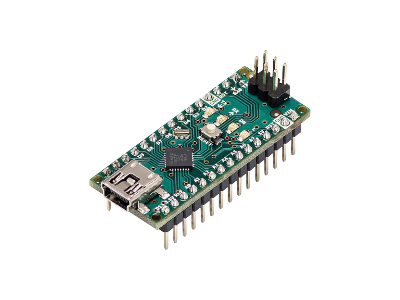
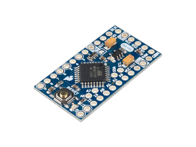
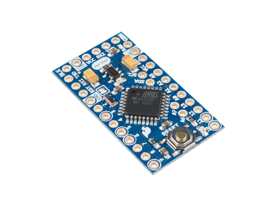
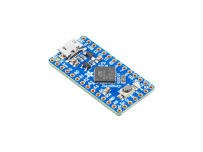
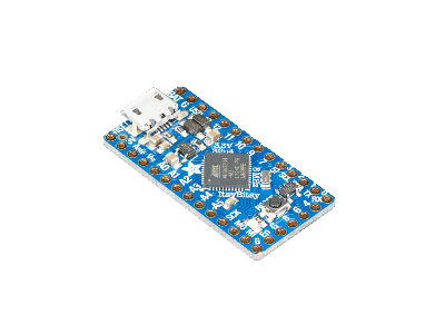
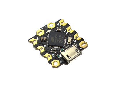
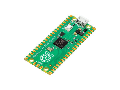
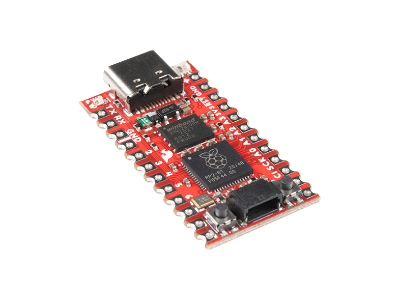
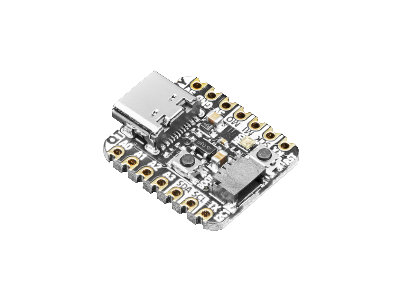
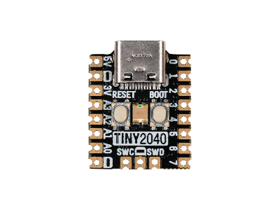
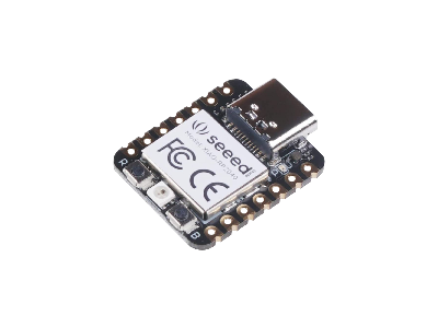
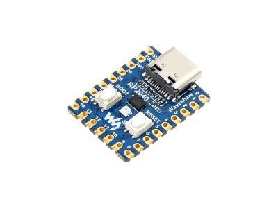
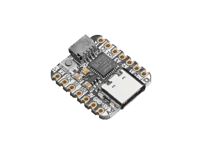
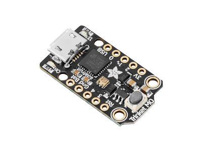
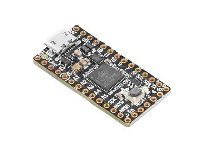
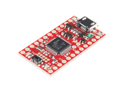
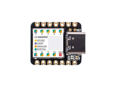
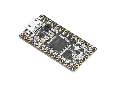
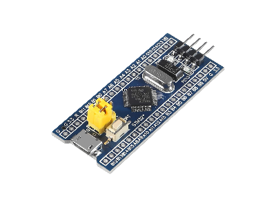
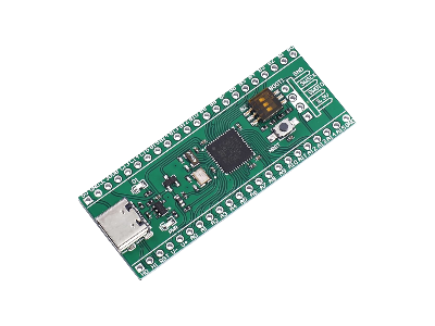
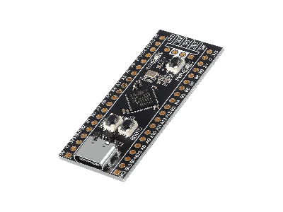
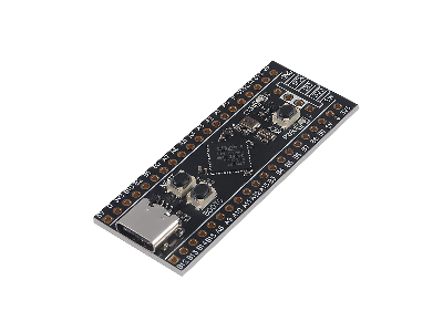
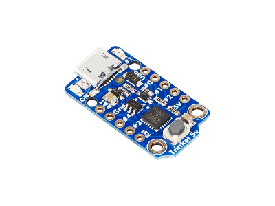
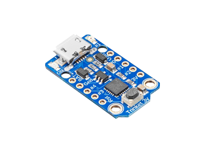
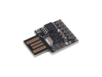
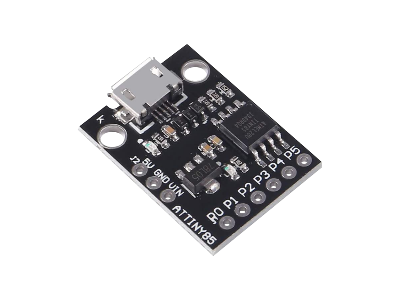
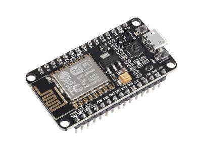
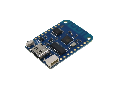
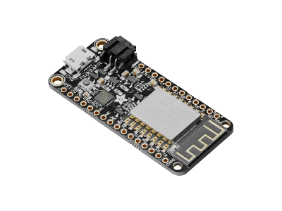
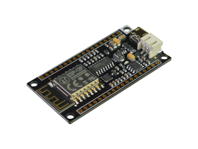
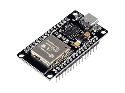
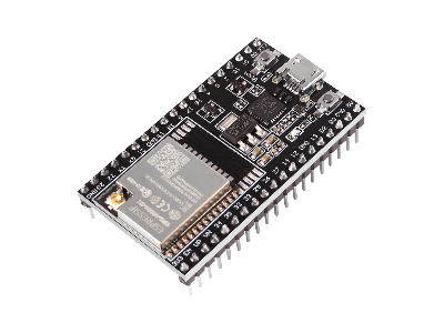
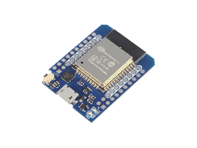
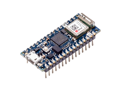
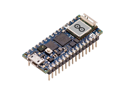
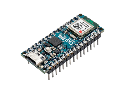
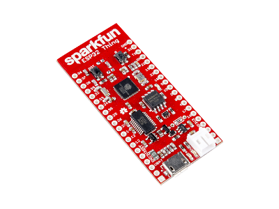
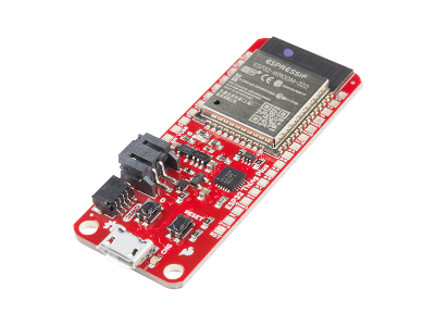
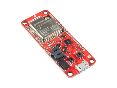
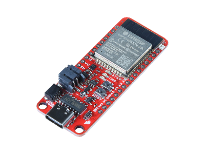
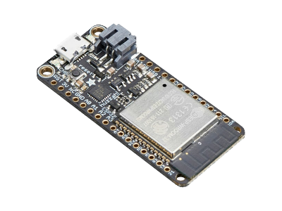
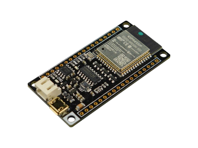
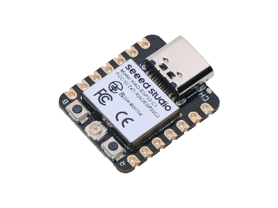
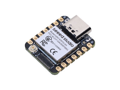
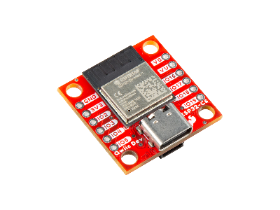
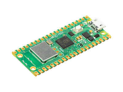
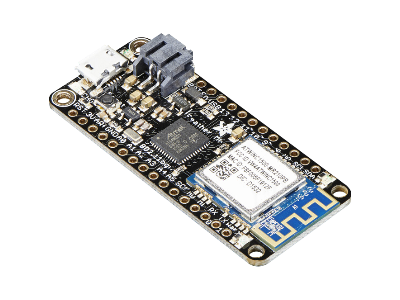
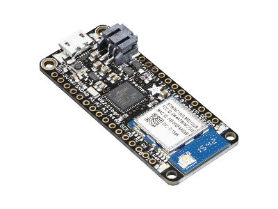
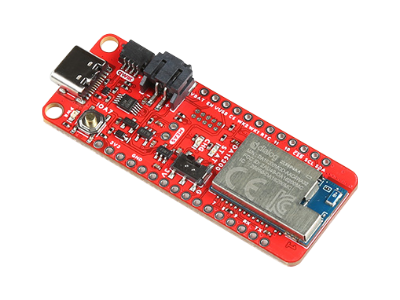
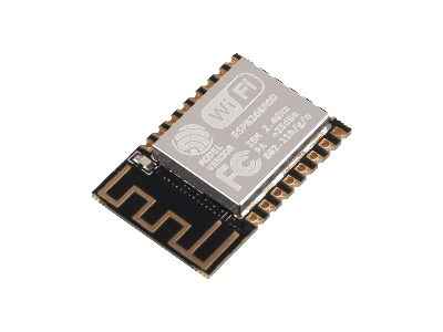
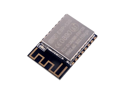
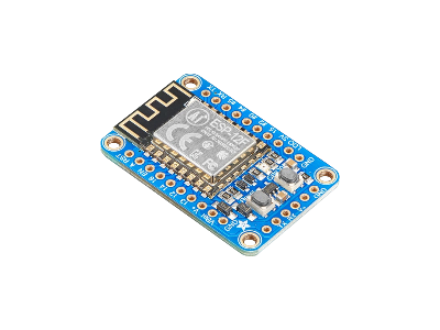
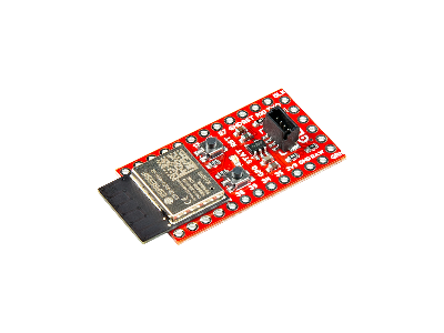
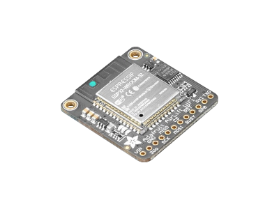
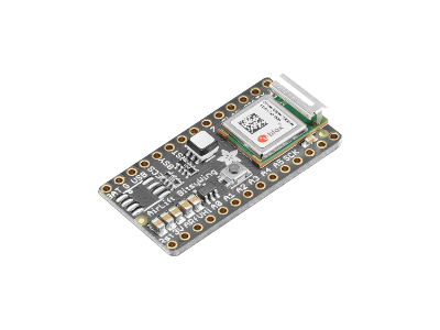
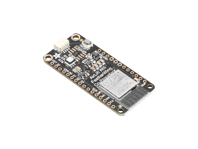
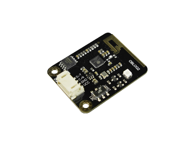
The output signals from the water sensors discussed here all have low data rates, so you don't need a high end microcontroller for processing the data. A low speed microcontroller with a UARTUniversal Asynchronous Receiver-Transmitter and I2CInter-Integrated Circuit. Also referred to as IIC or I2C. communication ports and small size will do the job, such as any of the options listed below.
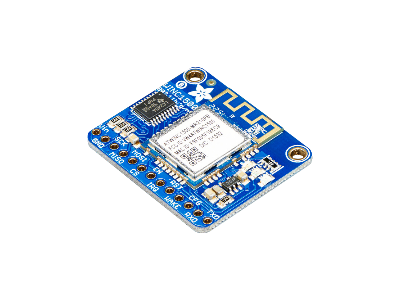
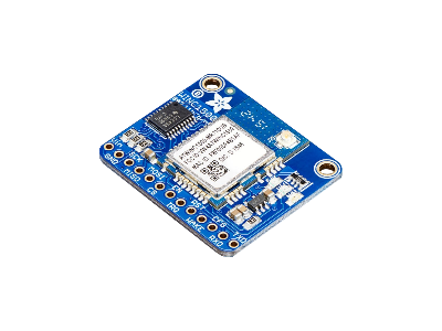
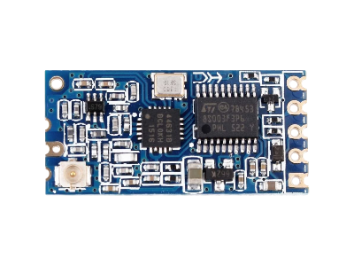
A transmitter and receiver (or both combined in a transceiver) is needed for wireless communication. Many microcontroller boards have a WiFi transceiver integrated into the board, which would be the simplest setup.
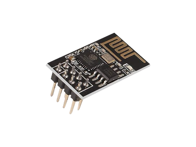
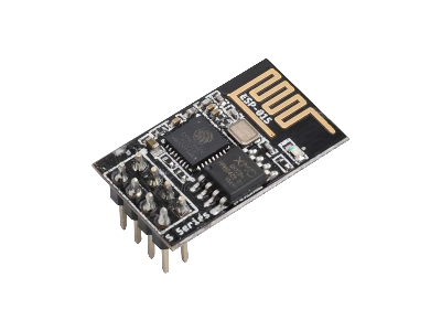
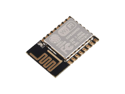
Alternatively, you could connect an external WiFi module to the serial port of the microcontroller to establish a WiFi connection.
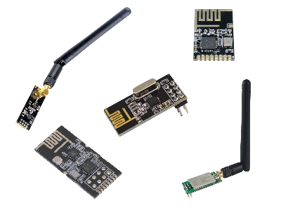
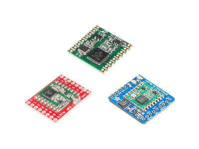
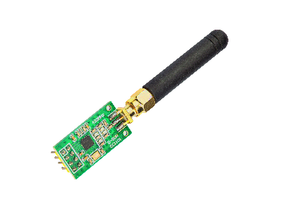
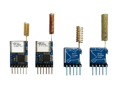
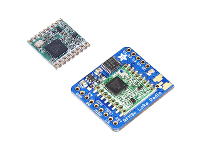
Another option is to use an RFRadio Frequency transceiver module to transmit data to the computer. Using RF modules would require more hardware compared to WiFi, since most computers already have WiFi, but RF modules generally have greater range, less power consumption, and are less prone to interference and/or traffic over your WiFi network.
You would need at least two RF modules, a transmitter connected to the microcontroller at the sensor and a receiver connected to the computer. RF modules transfer data to a computer over a UARTUniversal Asynchronous Receiver-Transmitter or SPISerial Peripheral Interface interface, which most SBCSingle Board Computers have, but if the computer does not have this interface then a conversion to USB with a microcontroller or USB Serial Adapter can be used.
Communication
When designing a monitoring system where a water sensor and microcontroller communicates with a computer or other device, some requirements need to be established on what data content will be exchanged and when that data is sent. Some things to consider are the following::
- Data transmission and communication failures
- Control of the measurement sampling rate
- Sensor health status
- Disabling/Enabling sensors remotely
Data Transmission
Measurements from the water sensors can be transmitted immediately when they occur so you can monitor and be alerted in real-time. If the communication fails, the data can be stored in the microcontroller memory temporarily while it continues trying to send the message until it is received. When the communication is successful, the record in the microcontroller memory can be cleared.
Measurement Sampling Rate
How often to make water measurements can be controllable from the computer so you can change it without reloading the embedded software on each microcontroller connected to the sensors. This means the embedded software on each microcontroller should include the capability of accepting commands from the computer to adjust the sensor sampling rate.
Sensor Health Status
If your sensor or microcontroller stopped running for some reason, you would have no way of knowing without some kind of periodic operational health status check. If the sensor and microcontroller is powered from a battery or has a backup battery, then the battery level should also be checked periodically.
How often the health status should be sent depends on your sensor and microcontroller power consumption requirements: more frequent status checks will consumes more power. You can setup the microcontroller to send the status over regular intervals like a beacon or you can ping the microcontroller from the computer or other device.
One advantage of the beacon approach it can provide a status over smaller time intervals (e.g., every second) if power consumption is not an issue. The advantage of pinging the microcontroller status from the computer is when and who to ping can easily be adjustable in the computer program for all your sensors, which avoids sensor transmission collisions when you have multiple sensors sending their status at the same time.
Disabling/Enabling Sensors
There are circumstances where you would want to temporarily disable a sensor from the computer or remotely, such as when making adjustments to the sensor or system. The embedded software in the microcontroller can be setup to accept a wireless command that would turn off sensor readings until another command is received to turn it back on.
Computer
The computer receives data from all the water sensors from a WiFi or RF receiver, reads in the data with a software interface, records the data, and can display the results on a monitor with some kind of dashboard.
If you don't have a computer available, it's worth mentioning that some WiFi microcontrollers, such as the ESP32 and the RPi Pico W, can also have a web server on them to create a web page displaying sensor results to your devices (phone, computer, tablet) over your network. Storing data on the microcontroller is limited, but you could store more data on an external SD card with a module or a USB flash drive with a USB host board.
Hardware
The computer hardware constantly monitors for any transmissions of water sensor data and records the data. This means that the computer needs to be on 24/7. A desktop computer will work if left on all the time, but are often used heavily on a daily basis which may be an issue sharing resources and updating the operating system constantly would interrupt your monitoring system.
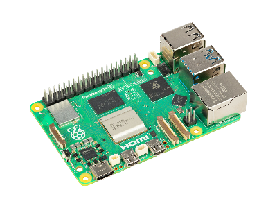
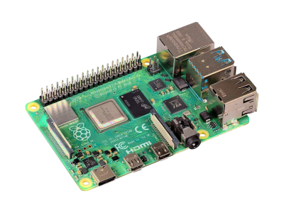
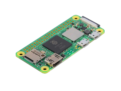
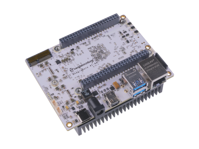
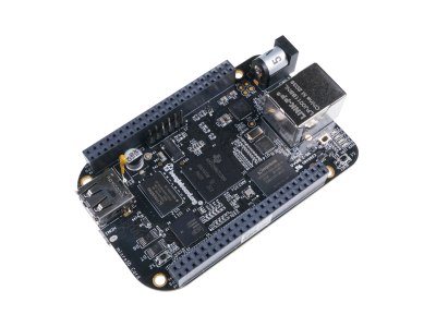
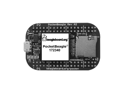
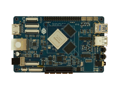
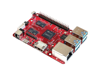
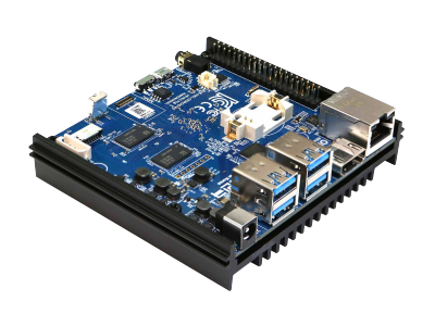
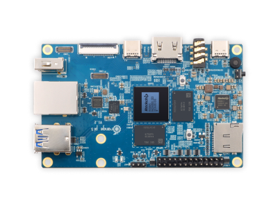
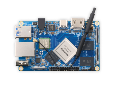
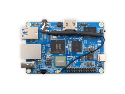
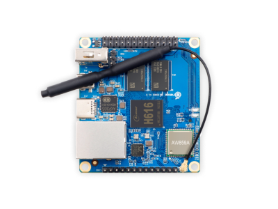
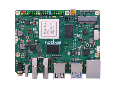
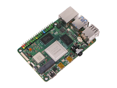
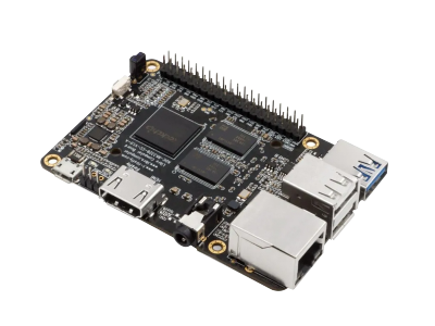
Single Board Computers (SBCSingle Board Computers) are relatively inexpensive compared to desktop or laptop computers, have a small form factor, can be left on all the time, don't require as many updates, and are typically not used for daily activities as much as a desktop computer. SBCs also consume a lot less power than a desktop computer and can last much longer on battery backup in the event of a power outage.
Software
The computer software can be designed to continuously read in the transmitted water sensor data, record the data, and display the results. The software can also be programmed to control the behavior of the sensors, such as changing the sampling rate, turning it off/on, or setting specific time intervals to make measurements.
I/O Interface
RF Interface
For RF modules the receiver is usually connected serially to the computer. This can be done directly through a UART/SPI interface on the GPIOGeneral Purpose Input Output of a SBC or through USB with a microcontroller or USB Serial Adapter. To collect data from the UART/SPI/USB port on the computer you can use the Python PySerial software interface. The functionality of this interface is described in more detail in the article Python PySerial I/O.
WiFi Interface
For WiFi communication, the software interface could be a TCP socket connection or a client-server configuration with the use of a standard protocol, such as HTTPHypertext Transfer Protocol, WebSocketWebSocket is a communication protocol, providing simultaneous two-way communication channels over a single Transmission Control Protocol (TCP) connection. WebSockets are typically run from a web browser connected to an application server that allows messages to be passed back and forth while keeping the connection open., and MQTTMQ Telemetry Transport (MQTT) is a lightweight publish-subscribe messaging protocol for small sensors and mobile devices, optimized for high-latency or unreliable networks. Historically, the "MQ" in "MQTT" came from the IBM MQ (then 'MQSeries') product line, where it stands for "Message Queue". However, the protocol provides publish-and-subscribe messaging (no queues, in spite of the name).. Since water sensor data consist of short messages that have a low bandwidth, MQTT is a good choice for handling a lot of overhead.
Graphical Interface
The user interface can be a desktop application GUIGraphical User Interface or web server developed by the programming language of your choice (Python, C++, Java, etc.). In Python, there are many desktop GUI frameworks you can use like TKinter, wxPython, PyQT, PySide 2, Kivy, PySimpleGUI, and PyGUI. All of these frameworks are cross-platform that work in Windows, macOS, and Linux. TKinter is a built-in module in Python and the easiest to get up and running and learn, has a small footprint, and is a good choice for small applications.
Another option for data monitoring is using a web page as the GUI from a server that can be ran locally or by a hosting service over the internet. The advantage of using a web page as the front end of a monitoring system is that it can be accessed remotely either by hosting it yourself using port forwarding on your local network or from a hosting service. Python has web frameworks such as Flask, FastAPI, or Django. Flask is the easiest to get setup and running (you can get set up with just a few lines of code).
An example of displaying data from water sensors is shown in the figure below. Gauge charts can be used to display current measurements of soil moisture, water consumption, water level, and water quality. Time series plots can show measurements throughout the day or whatever time period you want. Monthly averages throughout the year can be shown as a bar chart.
Alert Notifications
When you are away from your computer, the server back end can include the capability of automatically sending alert notifications by email and/or text messages that you can see on your phone when any of the water sensor measurements are outside their normal range. This additional feature of your monitoring system can be setup to allow you to turn the alert notifications on/off when not needed.
In Python you can automatically send emails using the built-in smtplib module and the ssl module can provide TLSTransport Layer Security encryption. If you are using a Python web framework (Flask, FastAPI, or Django), there are extensions for these frameworks that can send the email for you. For example, Flask has the extension Flask-Mail to automatically send emails.
Text messages can be sent using services such as Twilio or Textbelt, but they can also be sent for free through your email server with SMSShort Message Service Gateways using the same routines used for sending emails.
Conclusion
Implementing a water monitoring system gives you the capability of capturing data on water detection, soil moisture, water level, water consumption, and water quality. The hardware in this system includes water sensors, microcontrollers, transceivers, and a computer.
- Sensors are chosen based on the type of water measurements and other requirements of the application (ease of use, accuracy, power consumption, etc.).
- Low end microcontrollers and computers can be used for water monitoring.
- The type of transceivers used depends on range to the sensors: WiFi/RF transceivers can be used for short range, while RF transceivers can be used for distances beyond the range your WiFi network.
Recording water detection or usage on a computer connected to a network offers the capability of software to automatically send an alert notification by email and/or text messages that you can see on your phone when any of the water measurements are outside their normal range or pattern, such as a leak.






(0) Comments
Sign in to leave a comment
Sign In