Microcontrollers Overview
Updated: 17Aug2024 20:57:54 UTC 2024-08-17T20:57:54Z
Rating: (0 reviewsThis article has not been rated yet)
Microcontrollers (MCUMicrocontroller Unit) are designed for monitoring and/or control tasks that can operate as a stand-alone device or can be interfaced to another device such as a computer. Microcontrollers are a self contained micro-processing system that includes memory (RAMRandom Access Memory, Flash), timers, interrupts, ADCAnalog-to-Digital Converter (ADC, A/D, or A-to-D), and I/OInput/Output ports. This integrated system allows programming the MCUMicrocontroller Unit to control interfacing with external electronic devices.
This overview of microcontrollers covers its usage, MCU components, CPU, Memory, I/O Ports, Timers, Interrupts, and the System Bus.
Microcontrollers come packaged in stand-alone single ICIntegrated Circuit chips (e.g., Atmega328P, RP2040) where the number of pins, size, structure, and architecture vary depending on the model. Microcontrollers are also available in development boards (e.g., Arduino Uno Rev3, Raspberry Pi Pico) with the MCUMicrocontroller Unit built onto a single PCBPrinted Circuit Board along with the power conditioning circuit, reset, clock circuit, USBUniversal Serial Bus chip and connector, and I/OInput/Output connectors. Development boards utilize the MCUMicrocontroller Unit in a way that is easy to setup and interface to: plugging in power, USBUniversal Serial Bus to computer connection, loading software, and connecting I/OInput/Output.
Usage
You will find microcontrollers used in all kinds of devices these days from consumer products to electronic test equipment. Any device that measures, stores, controls, and/or displays data will probably have a microcontroller in it. Microcontrollers are programmable, small in size, and consume relatively low power, making them an ideal choice for many applications.
Suppose you want to periodically measure the temperature of a room and capture that data on your computer. A microcontroller can be programmed to read in the measured data from a temperature sensor at specific times and transfer the data (wired/wireless) to your computer. In general, a microcontroller can be setup to read in digital or analog signals in real-time and process, store, and transfer the data to other devices such as a computer and/or LCDLiquid Crystal Display screen for visualizing the data.
Microcontrollers are not suitable for all applications. For example, microcontrollers do not have the processing power for video streaming with real-time compression and transmission: they don't have enough speed, memory, and bandwidth. A Single Board Computer (SBCSingle Board Computer), like a Raspberry Pi or BeagleBone, is more suitable for video applications.
MCU Components
The basic structure of a microcontroller with its main internal components is shown in the figure below.
- CPUCentral Processing Unit:
- The CPUCentral Processing Unit is the main processor of the microcontroller responsible for executing instructions from programs stored in memory, data transfer operations, and coordinates activities with the peripherals. The CPUCentral Processing Unit reads, decodes, and executing instructions to perform Arithmetic, Logic, and Data Transfer operations.
- Memory:
- Used to store program code and data. The program memory is used to store instructions the CPUCentral Processing Unit executes. Data memory is required to store data while executing the instructions.
- I/OInput/Output Ports:
- Used to interface with external devices. Input devices, like switches and sensors transfer their signals through the inputs ports to provide information to the CPUCentral Processing Unit in the form of binary data. The output ports receive data from the CPUCentral Processing Unit and provides the appropriate response to external devices like LEDLight Emitting Diodes and LCDLiquid Crystal Displays.
- Serial Ports:
- Used for serial communication with external devices (e.g., UARTUniversal Asynchronous Receiver-Transmitter, I2CInter-Integrated Circuit. Also referred to as IIC or I2C., SPISerial Peripheral Interface).
- ADCAnalog-to-Digital Converter (ADC, A/D, or A-to-D):
- Input for converting an analog signal to digital. Many sensors are analog devices and their signal must be converted to digital data for the CPUCentral Processing Unit.
- Timers and Counters:
- Used in timing external events, delays, modulation, clock functions, frequency measurements, sampling ADCAnalog-to-Digital Converter (ADC, A/D, or A-to-D) data, I/OInput/Output timing, serial communication, etc. Timers increment on the CPUCentral Processing Unit clock pulse, whereas counters increment on external pulses.
- Interrupt Control:
- Used to provide an interrupt for a working program based on events (internal/external, hardware/software). Interrupts cause the processor to immediately respond to the event by executing a specific set of instructions.
- System Bus:
- A bus is a collection of parallel conductors that have a similar function. The system bus in a microcontroller connects the CPUCentral Processing Unit with other peripherals (memory, I/OInput/Output ports, timers, etc.).
- Clock Generator:
- Governs the speed at which the processor executes instructions and the synchronization of commands and data. The clock source can be either internal or external (e.g., crystal).
The following sections will cover each of these components in more detail.
CPU
The Central Processing Unit (CPUCentral Processing Unit) in a microcontroller is a complex circuit whose primary function is to execute programs that are stored in permanent non-volatile memory. The programs are created by the user on a PCPersonal Computer and downloaded onto the MCUMicrocontroller Units memory so it becomes a stand-alone processing system.
After the program is installed and the microcontroller is reset, it will fetch the program instructions from memory, decode its contents, and execute the instructions (usually repeatedly in a loop). The CPUCentral Processing Unit will then call upon the different components (I/OInput/Output, store/retrieve data from memory, set timers, serial communication, ADCAnalog-to-Digital Converter (ADC, A/D, or A-to-D), etc.) to execute their tasks according to the instructions in the program.
The CPUCentral Processing Unit performs the following operations.
-
Fetch Instructions:the CPUCentral Processing Unit reads instructions from memory -
Interpret Instructions:the instruction is decoded. The decoder also restores the encoded instructions to their original form. -
Fetch Data:needed if the instruction requires reading data from memory or I/OInput/Output -
Process Data:performing arithmetic and/or logical operations in the ALUArithmetic Logic Unit -
Write Data:if the instructions include writing data to memory of I/OInput/Output
The figure below shows typical components commonly found in a microcontrollers CPUCentral Processing Unit.
- Arithmetic and Logic Unit (ALUArithmetic Logic Unit):
- The ALUArithmetic Logic Unit performs arithmetic (addition, multiplication, etc.) and logical operations (AND, OR, etc.) within the processor. The ALUArithmetic Logic Unit takes two inputs and returns the result of the operation as its output along with some info about the result in the status register (result is zero, result is a negative value, operation produced an overflow/carry, etc.).
- Data Path:
- The data path executes instructions. It consists of the ALUArithmetic Logic Unit, set of registers, and CPUCentral Processing Unit's internal buses that allow data to flow between them.
- Control Unit:
- The control unit directs the operation of the processor by telling the data path what to do. It determines which operation in the program instructions should be executed next and to configure the data path accordingly.
- CPU Internal Registers:
- The CPUCentral Processing Unit contains a small internal storage area of internal registers for transient information. They are used for storing the values (operands) and results of arithmetic and logic operations by the ALUArithmetic Logic Unit and can keep track of where the next instruction is supposed to come from memory. This reduces the number of reads/writes to external memory which is slower. Memory contains a large amount of data and it takes time to access them by the bus. Registers are a quick source of data within the ALUArithmetic Logic Unit that can be directly accessed, which significantly improves the speed of the operations.
Bit Size
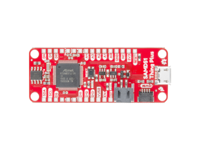
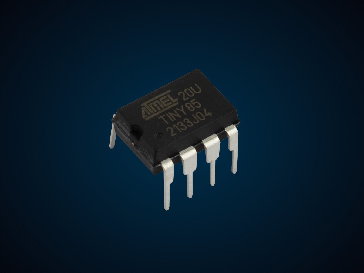
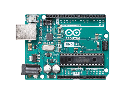
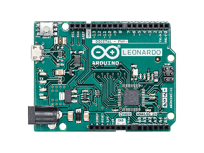
Microcontrollers can either be 8-bit, 16-bit, or 32-bit. The most common bit sizes are 8-bit and 32-bit shown in the table below. For example, ATmega328P MCUMicrocontroller Unit used in the Arduino Uno Rev3 is 8-bit. The RP2040 MCUMicrocontroller Unit in a Raspberry Pi Pico is 32-bit.
| MCU | Bit Size |
|---|---|
| ATmega328P | 8-Bit |
| ATmega32U4 | 8-Bit |
| ATtiny85 | 8-Bit |
| dsPIC33 | 16-Bit |
| MSP430 | 16-Bit |
| ESP8266 | 32-Bit |
| ESP32 | 32-Bit |
| RP2040 | 32-Bit |
| SAMD21 | 32-Bit |
| SAMD51 | 32-Bit |
| STM32F103 (Blue Pill) |
32-Bit |
| STM32F411 (Black Pill) |
32-Bit |
| MIMXRT1062 ARM Cortex-M7 (Teensy 4.0/4.1) |
32-Bit |
The bit size represents the data word length, the largest chunk of bits which a processor can handle at a time, used as an address, variable, register, and instruction set. The word length also corresponds to the size of the bus width and the I/OInput/Output port sizes will also generally follow the data bus size.
- 8-bit word has 28 values in the range 0 - 255
- 16-bit word has 216 values in the range 0 - 65,535
- 32-bit word has 232 values in the range 0 - 4,294,967,295
In general, going from 8 to 16 to 32 bit microcontrollers will operate on larger size data more efficiently with fewer restraints on resources. An 8-bit microcontroller can operate on numbers larger than its word length (> 255), but it requires more instruction cycles operating on the numbers in pieces 8-bits at a time. For instance, if you need to do an addition of 16-bit numbers in an 8-bit microcontroller, you will have to carry out 2 cycles of addition, whereas in a 16-bit microcontroller you can add the whole 16-bit numbers in one go.
A higher number of bits does not necessarily mean "better". An 8-bit microcontroller is more suitable for less compute intensive and low power battery applications (e.g., a device that turns a sprinkler on/off to water your lawn). A 32-bit microcontroller is more suitable for compute intensive applications (e.g., control an LCDLiquid Crystal Display touch screen, FFTA Fast Fourier Transform (FFT) is an efficient numerical algorithm used in signal processing to decompose a function or a sequence of values into its constituent frequencies. computations, processing sound, image processing, Ethernet interface, etc.) where more precision is needed at higher speeds, but it will consume more power.
Clock Speed
The clock generator is an oscillator circuit that produces a clock signal for use in synchronizing a microcontroller's operation. In order to control the flow of data between the different components of the microcontroller one needs a clock. The clock is like a drumbeat that tells everything when to act.
The clock governs the speed at which the processor executes instructions, the synchronization of commands and data, the rate of serial communication signals, the amount of time needed to perform an analog-to-digital conversion, and much more. The clock source can be either internal or external (e.g., crystal). Externally, the crystal oscillator (along with PLLPhase-Locked Loops and other circuitry) is typically used for the generation of clock signals required for clocking the data.
The clock speed of an microcontroller is how long it takes to execute one instruction. Microcontrollers typically operate at clock speeds ranging in the megahertz (MHz). Below is a comparison of the different clock speeds for common microcontrollers.
| MCU | Clock Speed |
|---|---|
| ATmega328P | 16MHz |
| ATmega32U4 | 16MHz |
| ATtiny85 | 16MHz |
| ESP8266 |
80MHz (default) to 160MHz |
| ESP32 | 240MHz |
| RP2040 | 133MHz |
| SAMD21 | 48MHz |
| SAMD51 | 120MHz |
| STM32F103 (Blue Pill) |
72MHz |
| STM32F411 (Black Pill) |
84MHz/100MHz |
| MIMXRT1062 ARM Cortex-M7 (Teensy 4.0/4.1) |
600MHz |
Memory
Microcontrollers usually contain volatile memory, such as RAMRandom Access Memory, and non-volatile memory, such as Flash and/or EEPROMElectrically Erasable Programmable Read-Only Memory. The contents of volatile memory are lost if the microcontroller loses power, whereas the contents of non-volatile memory persists between power cycles. A description of the different types of memory in microcontrollers is given below.
- RAMRandom Access Memory or SRAMStatic Random Access Memory:
- Volatile memory that is the working data space for storing transient data, such as variables, the heap, and the stack, and can be written to and read from during program execution.
- Flash:
- Non-volatile memory used to store programs (code) and also any constant data values. It can be read, erased, and written to.
- EEPROMElectrically Erasable Programmable Read-Only Memory:
- Non-volatile memory to hold data that needs to persist between software changes and power cycles. It can be erased and written to, making it useful for logging system malfunctions and fault data during program execution. It is also useful for storing special data or configuration data that must be retained during a power failure but might need to be changed periodically.
In most microcontrollers, RAM is usually smaller in size than flash memory because it costs more. RAM has lower latency (faster read/write) than flash memory. Some microcontrollers, like the RPiRaspberry Pi Pico, do not have EEPROM and rely entirely on Flash memory to store permanent data. While other microcontrollers, like the Arduino Uno Rev3, use the Flash memory to store programs and rely on EEPROM for storing permanent data.
ATmega328P Memory in the Arduino Uno Rev3, Nano, and Mini
The Arduino Uno Rev3, Nano, and Mini ATmega328P microcontrollers have 32KB (0.5KB is used for Bootloader) of flash memory, 2KB of SRAM, and 1KB of EEPROM.
The ATmega328P EEPROM is not only scarce with a limit of 1024 bytes, but also has the limitation that it can only save one byte: you can only store 8-bit numbers, which includes integer values between 0 and 255.
You might think to just use the 32KB Flash memory instead EEPROM to write your data to. Normally, the ATmega328P only allows you to write to flash memory when when it's in bootloader mode. The standard bootloader allows you to write to flash when a new program is being installed, but does not allow runtime programs to write to flash. However, there is a hack to the bootloader that does allow you to run functions that enable you to write to flash (check out this Hackaday post on the subject).
RP2040 Memory in the RPi Pico
The RPiRaspberry Pi Pico RP2040 microcontroller has 264KB of SRAM and 2MB of QSPIQuad Serial Peripheral Interface (QSPI) is a serial communication interface designed for talking to flash chips by using 4 data lines. Flash. The Pico does not have a separate EEPROMElectrically Erasable Programmable Read-Only Memory non-volatile memory like the Arduino. For its flash memory, QSPIQuad Serial Peripheral Interface (QSPI) is a serial communication interface designed for talking to flash chips by using 4 data lines. is faster than traditional SPISerial Peripheral Interface because it uses 4 data lines (I0, I1, I2, and I3) as opposed to just 2 data lines (MOSIMaster Out Slave In (MOSI) is the SPI data output line from the master device and MISOMaster In Slave Out (MISO) is the SPI data output line from the slave device) on the traditional SPISerial Peripheral Interface.
Note that the RP2040 datasheet states that it has 264KB of internal RAMRandom Access Memory, but when you check the RAMRandom Access Memory availability using commands (mem_info) on the RPiRaspberry Pi Pico, it outputs only about 192KB of RAMRandom Access Memory available for use. This is because some of the memory is used by the Python interpreter, stack, buffers, etc.
Besides the SRAMStatic Random Access Memory main memory, there are two other dedicated RAMRandom Access Memory blocks that may be used in some circumstances:
- If flash XIPExecute In Place (XIP) is a method of executing programs directly from long-term storage rather than copying it into RAM caching is disabled, the cache becomes available as a 16KB memory
- If the USBUniversal Serial Bus is not used, the USBUniversal Serial Bus data DPRAMDual-Ported RAM (DPRAM) is a type of random-access memory that allows multiple reads or writes to occur at the same time, or nearly the same time, unlike single-ported RAM which allows only one access at a time. can be used as a 4KB memory
The RP2040 also has 16KB of ROMRead-Only Memory, but this is used for the flash boot sequence, flash programming routines, USBUniversal Serial Bus mass storage device with UF2UF2 is a firmware file format developed by Microsoft that allows for flashing microcontrollers over USB. It appears as a Mass Storage Device (USB Drive) when attached to your computer, so you can copy firmware to a USB drive instead of having to burn it using other tools. support, and utility libraries such as fast floating point.
MCU Internal Memory Comparison
The table below provides a comparison of internal memory (RAM, Flash, and EEPROM) for different microcontrollers. Some microcontrollers, such as the RP2040, ESP8266, and ESP32, support external memory with an SPISerial Peripheral Interface Flash chip (2MB/4MB/16MB).
| MCU | Memory |
|---|---|
| ATmega328P |
|
| ATmega32U4 |
|
| ATtiny85 |
|
| ESP8266 |
|
| ESP32 |
|
| RP2040 |
|
| SAMD21 |
|
| SAMD51 |
|
| STM32F103 (Blue Pill) |
|
| STM32F411 (Black Pill) |
|
| MIMXRT1062 ARM Cortex-M7 (Teensy 4.0/4.1) |
|
I/O Ports
The I/OInput/Output ports on a microcontroller are used to send and receive data to the outside world. These ports have registers that are connected to the CPUCentral Processing Unit using the data bus and to the outside world with physical pins on the side of the microcontroller. Three registers control the behavior of the pins.
- Data Direction Register (DDR):
- The input/output function of the pin is configured by a bit in the DDR. Each I/OInput/Output port has its own DDR that contains one bit for each pin of the port. Each pin of a port can be configured differently.
- Port Register (PORT):
- Controls the high/low voltage level of the output pins.
- Port Input Register (PIN):
- The PIN register contains the current state (high/low) of a pin, whether the pin is configured as an input or output.
Often the I/OInput/Output ports have alternative functions (serial communication, ADCAnalog-to-Digital Converter (ADC, A/D, or A-to-D), etc.) to reduce the number of pins on the microcontroller and the size of the chip.
Serial Ports
Microcontrollers usually contain several pins for serial communication with other devices, often with multiple instances of a particular interface with the purpose of communicating with more than one device.
Serial communication sends data sequentially, one bit at a time, where synchronization between the transmitter and receiver must be maintained to allow both to be expecting transmission/reception at the same time. There are two different ways of maintaining synchronization.
- Synchronous Communication:
- Has data sent in a continuous stream using a separate line with a pulsed clock signal for synchronization. Data bits are sent and received on the rising or falling edge of the common clock's signal. Examples of synchronous communication are I2CInter-Integrated Circuit. Also referred to as IIC or I2C. and SPISerial Peripheral Interface.
- Asynchronous Communication:
- There is no clock line. Data is sent in the form of packets with start and stop bits added, with both the transmitter and receiver configured to the same baud rate. Data can be sent intermittently rather than a steady stream. Examples of asynchronous communication are UARTUniversal Asynchronous Receiver-Transmitter and RS232.
There are three different transmission modes.
- Simplex Mode:
- The communication is unidirectional one-way where only one of the two devices can transmit and the other can only receive. Examples that use the simplex mode of transferring data are a keyboard, mouse, and monitor.
- Half-Duplex Mode:
- each device can transmit or receive, but not at the same time. When one device is sending, the other device must be receiving. An example that uses half-duplex mode is a Walkie-Talkie where two parties take turns speaking.
- Full-Duplex Mode:
- Each device can transmit and receive at the same time. An example using full-duplex mode is a telephone line where both parties can talk at the same time.
The transmission speed is characterized by the baud rate.
- Baud Rate:
- Data transmission rates are typically specified as baud, which is the symbol rate. If the system has only 2 symbols (0 and 1) transferred, then the baud is equivalent to bits per second (bpsbits per second) (e.g., 9600 baud means that data is being transferred at 9600 bits per second).
UART
The Universal Asynchronous Receiver Transmitter (UARTUniversal Asynchronous Receiver-Transmitter) uses two data lines, one to transmit (TXTransmit) and another to receive (RXReceive), for half-duplex or full-duplex communication.
- TXTransmit:
- output transmitting data
- RXReceive:
- input receiving data
Since UARTUniversal Asynchronous Receiver-Transmitter is asynchronous and has no clock signal line, the transmission data must have bits that indicate the start and end of the message. Data is sent over the bus in the form of a packet, which consists of a start bit, data frame (5 to 9 bits), a parity bit, and stop bits. Also, both devices must be configured to operate at the same baud rate. The user must select a baud rate from a set of possible rates on the devices because they depend on the system clock, but are generally within the range of 9600bpsbits per second and 115,200bpsbits per second.
I2C
Inter-Integrated Circuit (I2CInter-Integrated Circuit. Also referred to as IIC or I2C.) is a synchronous bus that uses two wires, Serial Clock Line (SCLSerial Clock (SCL) is the output clock signal line from the master device. Also referred to as SCK, SCLK, or CLK.) and Serial Data Line (SDASerial Data Line), for half-duplex communication over a short distance. I2C is also referred to as a Two-Wire Interface (TWITwo-Wire Interface). It operates on the master-slave principle with the microcontroller as the master and peripheral devices as the slaves.
- SDA (Serial Data Line):
- used by the master or slave to transmit/receive data
- SCL (Serial Line Clock):
- used by the master to transmit the clock signal
Both the SDA and SCL lines have pull-up resistors (RPU) that are pulled up to VDDVoltage Drain Drain (VDD) is the supply voltage at the Drain of a transistor. The double subscript notation of repeating letters "DD" is used to denote a power supply voltage that is relative to ground. , the logic level supply of the MCUMicrocontroller Unit and device. The I2C bus drivers are open drain drivers, which means they can drive drive their output low, but cannot drive it high. For the line to be able to go high there has to be pull-up resistors to VDD. Some MCUs and devices already have pull up resistors within them for the SDA and SCL pins, where external pull up resistors are not needed.
The original I2C bus had a maximum speed of 100kHz, now called the standard mode. Most applications still use this speed, since it is usually sufficient for transferring data with most modules, such as sensors, memory modules, and LCDLiquid Crystal Display displays. The I2C protocol specifies this standard mode and higher speed modes, as given in the table below, but not all I2C devices support these modes.
| Mode | Speed |
|---|---|
| Standard Mode (Sm) | 100kbps |
| Fast Mode (Fm) | 400kbps |
| Fast Mode Plus (Fm+) | 1Mbsp |
| High-Speed Mode (Hs) | 3.4Mbps |
| Ultra-Fast Mode (UFm) | 5Mbps |
One of the main advantages of I2C is the capability of adding as many peripheral devices as you want to the bus (SDA and SCL lines) as long as the maximum bus capacitance of 400 pF is not exceeded. This is illustrated in the figure below.
SPI
The Serial Peripheral Interface (SPISerial Peripheral Interface) provides synchronous full-duplex communication on the master-slave principle using four lines.
- MOSI (Master Out, Slave In):
- used by the slave to transmit data to the master
- MISO (Master In, Slave Out):
- used by the master to transmit the clock signal
- SCLK (System Clock):
- used by the master to transmit the clock signal. Also referred to as SCK, SCL or CLK.
- SS (Slave Select):
- used by the master to select a slave
SPI operates on the master-slave principle with the microcontroller as the master and peripheral devices as the slaves. Two different wiring configuration can be used for multiple slave devices: the independent slave configuration and daisy chain slave configuration.
In the independent slave configuration, the master uses different SSSlave Select (SS) is the SPI output line from the master device to indicate that data is being sent. Also referred to as Chip Select (CS). pins (using GPIOGeneral Purpose Input Output output pins on a microcontroller) for each slave device shown in the figure below. When the master wants to communicate with a particular slave, it pulls its SSSlave Select (SS) is the SPI output line from the master device to indicate that data is being sent. Also referred to as Chip Select (CS). pin LOW during the duration of the communication exchange.
In the daisy chain slave configuration, the master uses only one SSSlave Select (SS) is the SPI output line from the master device to indicate that data is being sent. Also referred to as Chip Select (CS). pin (a GPIOGeneral Purpose Input Output output pins on a microcontroller) connected to all the slave devices shown in the figure below. When the master wants to communicate with a particular slave, it pulls its SSSlave Select (SS) is the SPI output line from the master device to indicate that data is being sent. Also referred to as Chip Select (CS). pin LOW to initiate communication, sends data over its MOSIMaster Out Slave In (MOSI) is the SPI data output line from the master device to the first slave device in the chain, which then flows from one slave to the next in the chain.
SPI is the fastest protocol compared to UARTUniversal Asynchronous Receiver-Transmitter and I2CInter-Integrated Circuit. Also referred to as IIC or I2C.. Communication speeds depend on the clock frequency of the microcontroller master device using a frequency supported by slaves devices, which are typically up to a few MHz.
Analog I/O
Analog Input
Most microcontrollers come with an Analog-To-Digital Converter (ADCAnalog-to-Digital Converter (ADC, A/D, or A-to-D)) to read in a continuous analog signal from an input pin and translate it into a digital number proportional to the signal. Many sensors have an analog voltage output related to the physical property being sensed. For example, a TMP36 temperature sensor produces an output voltage linearly related to the ambient temperature.
Most microcontrollers include an internal ADC with a subset of GPIOGeneral Purpose Input Output pins that you can use to interface with the ADC. The input pins are typically labeled with an 'A' in front of their label. For example, the analog input pins for the Arduino Uno R3 are labeled A0 through A5, the Arduino Nano pins are labeled A0 through A7, and the RPi Pico pins are labeled ADC0 through ADC2.
The most common ADC in MCUMicrocontroller Units is a SARSuccessive Approximation Register where an internal sample and hold (S/H) capacitor is charged to the input voltage (sample) and then disconnected (hold) to measure the time in number of clock cycles it takes to discharge across an internal resistor and zoom in on the correct ADC output.
The resolution of MCU ADCs typically range from 8-bit to 12-bit. For instance, the Arduino Uno R3 and Nano has a 10-bit ADC, whereas the RPi Pico ADC is 12-bit. Both of these MCUs will be covered below.
ATmega328P ADC in Arduino Uno Rev3 and Nano
The ATmega328P MCU used in the Arduino Uno R3 and Nano has a built in 10-bit ADC. The specs for this ADC from ATmega328P Datasheet (PDF) are given in the table below.
| Parameter | Spec |
|---|---|
| Voltage Supply (Vs) | 1.8V to 5.5V |
| Resolution | 10-Bit |
| Number of Channels | 8 single-ended inputs |
| Sampling frequency @ 5V operation and 125KHz ADCAnalog-to-Digital Converter (ADC, A/D, or A-to-D) sampling clock |
9.6kHz |
| Sampling frequency @ 5V operation and 200KHz ADCAnalog-to-Digital Converter (ADC, A/D, or A-to-D) sampling clock |
15kHz |
| Conversion time | 13 ADCAnalog-to-Digital Converter (ADC, A/D, or A-to-D) clock cycles, 65μs to 260μs |
| ADCAnalog-to-Digital Converter (ADC, A/D, or A-to-D) clock range for good results | 50kHz to 200kHz |
|
Absolute Accuracy (INLIntegral Non-Linearity + DNLDifferential Non-Linearity + quantization error + gain & offset error) |
2 LSBThe Least Significant Bit (LSB) in a binary number is the bit that represents the smallest place value carrying the lowest weight. It is also sometimes referred to as the low-order bit or right-most bit due to the convention in positional notation of writing less significant digits further to the right. |
Note that although the ATmega328P ADC has 8 channels, the Arduino Uno R3 only makes use of 6 channels (A0 - A5) to interface with, but the Arduino Nano board makes use of all the channels (A0 - A7).
RP2040 ADC in RPi Pico
The RPi Pico has internal 12-bit ADC with 4 channels and a sampling rate up to 500kspsKilo Samples Per Second (1000 samples/s) (using an independent 48MHz clock). The ADC specs and block diagram provided below are from the RP2040 Datasheet (PDF).
| Parameter | Spec |
|---|---|
| Voltage Supply (Vs) | 1.8V to 3.3V |
| Resolution | 12-Bit with 8.7 ENOBEffective Number Of Bits is a measure of the dynamic range of an ADC |
| Number of Channels | 4 |
| Sampling Frequency | 500kSPSKilo Samples Per Second (1000 samples/s) |
| Conversion time | 96 clock cycles, 2μs |
| ADCAnalog-to-Digital Converter (ADC, A/D, or A-to-D) clock | 48MHz |
| DNLDifferential Non-Linearity | 8.9 LSBThe Least Significant Bit (LSB) in a binary number is the bit that represents the smallest place value carrying the lowest weight. It is also sometimes referred to as the low-order bit or right-most bit due to the convention in positional notation of writing less significant digits further to the right. |
| INLIntegral Non-Linearity | 7.85 LSBThe Least Significant Bit (LSB) in a binary number is the bit that represents the smallest place value carrying the lowest weight. It is also sometimes referred to as the low-order bit or right-most bit due to the convention in positional notation of writing less significant digits further to the right. |
MCU ADC Comparison
The table below provides a comparison of the different ADCs for common microcontrollers. The number of channels (nCH) listed in the table is the maximum the MCU provides, but some microcontroller boards may not break out of all the channels into pins or may use some of the channels for a different purpose (temperature sensor, system voltage, etc.).
| MCU | Bits | nCH |
|---|---|---|
| ATmega328P | 10-Bit | 8 |
| ATmega32U4 | 10-Bit | 12 |
| ATtiny85 | 10-Bit | 4 |
| ESP8266 | 10-Bit | 1 |
| ESP32 | 12-Bit | 18 |
| RP2040 | 12-Bit | 4 |
| SAMD21 | 12-Bit | 20 |
| SAMD51 | 12-Bit | 16 |
| STM32F103 (Blue Pill) |
12-Bit | 10 |
| STM32F411 (Black Pill) |
12-Bit | 16 |
| MIMXRT1062 ARM Cortex-M7 (Teensy 4.0/4.1) |
12-Bit | 20 |
Analog Output
Two common methods to produce an analog output with a microcontroller are Pulse-Width Modulation (PWMPulse-Width Modulation) or using a Digital-to-Analog Converter (DACDigital-to-Analog Converter (DAC, D/A, or D-to-A)).
- Pulse-Width Modulation (PWM):
- Most microcontrollers do not have a DAC, but still can produce analog output with the PWM digital output. PWM signals are rectangular waves, varying from zero to a maximum voltage, by toggling a digital output pin at a specific frequency and duty cycle. The desired analog voltage output level can be achieved by changing the PWM duty cycle in the microcontroller program: the output voltage is the logic-high voltage times the duty cycle.
- PWM RC Filter:
- A simple RC filter can be used to flatten the PWM signal. The RC filter has some limitations due to residual "waviness" in the output.
- PWM Low-Pass Filter:
- A low-pass filter can be used to remove the high-frequency components of the PWM signal, resulting in a smooth analog output. The filter can be configured to produce a signal that varies periodically, such as a sinusoidal, triangular, or sawtooth wave.
- Digital-to-Analog Converter (DAC):
- Some microcontrollers have a DAC that can convert a digital signal to an analog output signal. This can be used to generate a precise analog voltage depending on the bit resolution of the DAC. The table below provides the bit resolution (Bits) and number of channels (nCH) for different DACs in common microcontrollers.
| MCU | Bits | nCH |
|---|---|---|
| ATmega328P | None | |
| ATmega32U4 | None | |
| ATtiny85 | None | |
| ESP8266 | 8-Bit | 2 |
| ESP32 | 8-Bit | 2 |
| RP2040 | None | |
| SAMD21 | 10-Bit | 1 |
| SAMD51 | 12-Bit | 1 |
| STM32F103 (Blue Pill) |
None | |
| STM32F411 (Black Pill) |
None | |
| MIMXRT1062 ARM Cortex-M7 (Teensy 4.0/4.1) |
None | |
Timers and Counters
One of the most useful features of a microcontroller is the capability of performing time related tasks. Microcontrollers can be setup to read inputs at specific times, switch an external device on/off at specific times, or generate pulsed output at the right frequencies and pulse width to control the speed of motors.
Timers and counters are used in timing external events, delays in a program or hardware components, clock functions, frequency measurements, sampling ADCAnalog-to-Digital Converter (ADC, A/D, or A-to-D) data, general I/OInput/Output timing and Pulse Width Modulation (PWMPulse-Width Modulation), serial communication timing, etc.
Timers are basically counters that can either increment/decrement on CPUCentral Processing Unit clock pulses for timing events or on external pulses for counting events (the direction up/down is either fixed or configurable). The goal of using a timer in a microcontroller is twofold: (1) detector and/or capture external timing event and (2) generate timing events to control external devices.
Timer Resolution
The timer resolution is specified by b-bits, where the count value is in the range [0, 2b-1]. For example, the ATmega328P MCUMicrocontroller Unit in the Arduino Uno R3 has three timer/counters called Timer0, Timer1, and Timer2. These timers have two different resolutions: Timer0 and Timer2 are 8-bit timers, whereas Timer1 is a 16-bit timer. The 8-bits means 28 = 256 values from 0 to 255, whereas 16-bit means 216 = 65536 values from 0 - 65535 for higher resolution.
Once a counter reaches its maximum value, it will tick back to zero (this is called overflow). Timers generally raise an interrupt whenever they experience an overflow and a status flag is set to notify the processor of this event so rollover events may be counted.
The timer module usually provides mode bits which allow the user to select prescaler values (1, 8, 64, 256, 1024, ...) to scale down the input clock frequency and slow down the counter rate to measure a longer duration.
The prescaler effectively extends the range of the timer, but comes at the cost of coarser time step resolution.
Detecting External Events
Once the input timer is configured with the appropriate prescaler, a method for detecting the event to needs to be chosen to know when to increment the counter. There are two main methods for detecting input events: polling and interrupts.
Polling is where the microcontroller constantly polls a flag for a logic high signal when an event occurs on the physical pin. A more efficient use of resources is using interrupts to detect the event, which allow a microcontroller to perform other tasks until the interrupt event occurs. Most microcontrollers are equipped with built-in interrupt systems with their timer input modules.
Interrupts
Interrupts allow the microcontroller take over the flow of a program to respond to a higher priority event where a state change is detected. When an interrupt occurs, a signal is sent to the CPUCentral Processing Unit to begin executing different code that is written to respond to the interrupt after the end of the current instruction.
The code that executes for an interrupt is called the Interrupt Service Routine (ISRInterrupt Service Routine) that is programmed by the user to take specific actions. Once the ISR is complete, the program will resume where it left off.
There are usually different interrupts available on microcontrollers. Two main interrupts that are often used are the following.
- Real Time Interrupt (RTIReal Time Interrupt):
- Provides a regular, periodic interruption in the main program flow. This is useful for updating a real time clock or checking the battery level.
- External Interrupt Request (IRQInterrupt Request (IRQ) pins are capable of receiving an external signal to interrupt a running program and alter its behavior.):
- An external controller hardware pin that responds to voltage level state changes. When a state change occurs on the pin an interrupt is generated and the associated interrupt service routine is executed.
Microcontrollers usually have multiple sources of interrupts, like the input pins going high, timer overflow, ADC completion, etc.
System Bus
The system bus is a group of parallel wires that connect the CPUCentral Processing Unit with other peripherals (memory, I/OInput/Output ports, timers, etc.). Most microcontrollers are equipped with an address bus, a data bus, and a control bus. Together, these three make up the system bus.
- Address Bus:
- The address bus carries only the information regarding the address of data, the physical location of the data in memory, that the processor will read data from or write data to. The addressing signals pass from the CPUCentral Processing Unit to memory, I/OInput/Output (or peripherals), and other addressable devices around the processor.
- Data Bus:
- The data bus routes data to/from different peripherals within the microcontroller. Data moving in and out of the data bus is bi-directional, since the processor reads and writes data. The data bus "width" is the MCUMicrocontroller Unit bit size, which is typically 8-bits, 16-bits, 32-bits, or 64-bits.
- Control Bus:
- The control bus manages the information flow between components indicating whether the operation is a read or a write and ensuring that the operation happens at the right time.
Selecting A Microcontroller
Choosing a microcontroller depends on your application needs. There are plenty of options to choose from with different bit sizes, clock speeds, multiple CPUCentral Processing Unit cores, memory, operating voltage, power consumption, number of I/OInput/Output pins, interfaces for communication, and package size.
In addition to the microcontroller features, an important factor to consider is the amount of documentation and other resources available (tutorials, forums) to understand the device and troubleshoot any problems that occur.
Here are some common microcontroller board selections for different use cases.
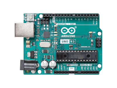
- For something simple or for prototyping, the Arduino Uno R3 with an ATmega328P MCU is a good choice.
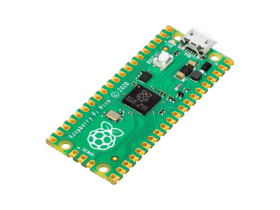
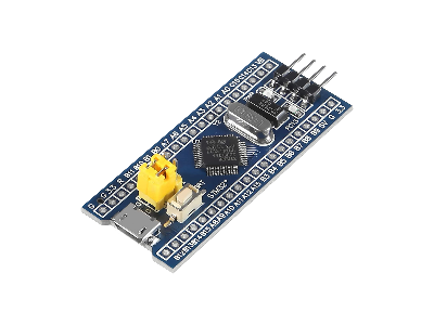
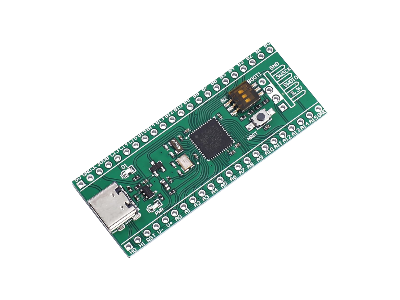
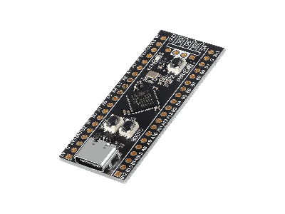
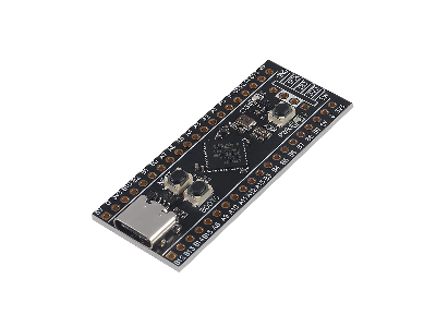
- If you need a mid range microcontroller, then the RP2040 in RPiRaspberry Pi Pico, SAMD21, or blue/black pill STM32 will do.
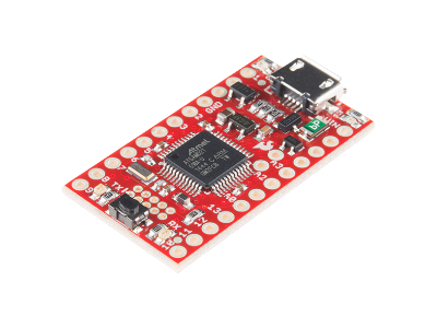
- If you need more processing power, the Teensy 4.0/4.1 or higher end STM32's are the fastest.
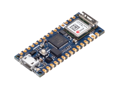
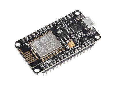
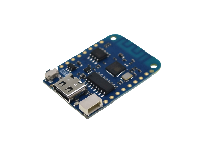
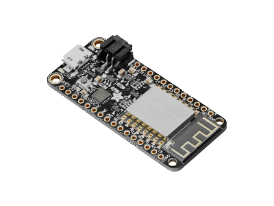
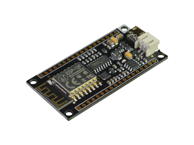
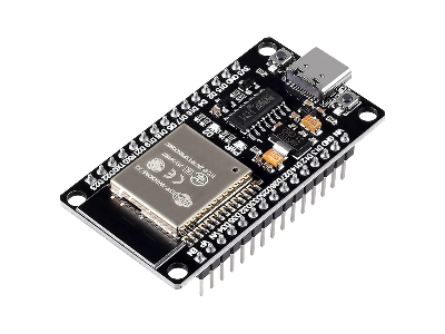
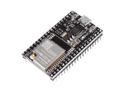
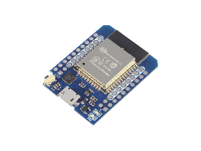
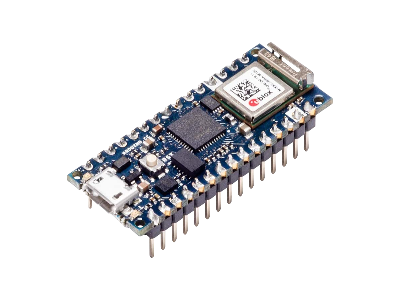
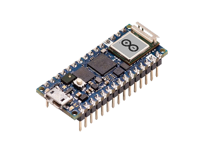
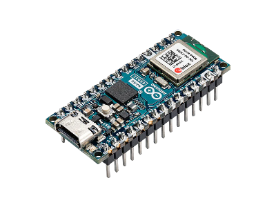
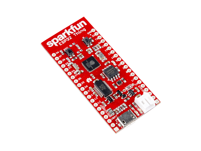
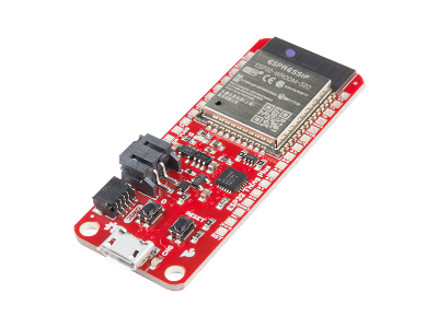
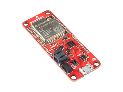
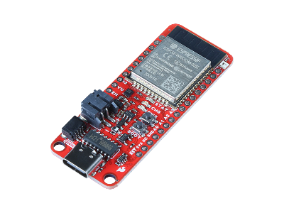
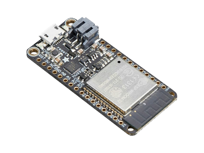
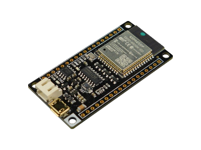
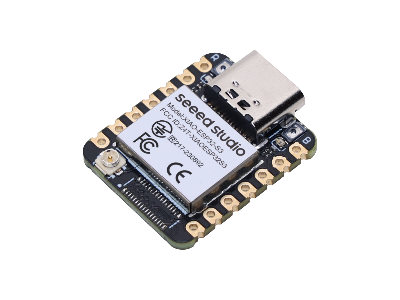
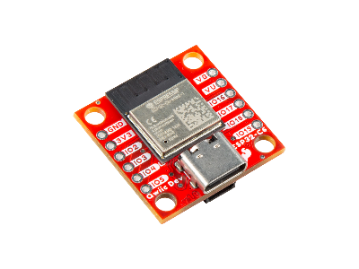
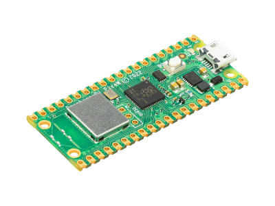
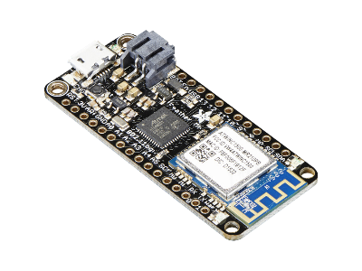
- For WiFi applications an ESP8266, ESP32, RPiRaspberry Pi Pico W, or Arduino Nano 33 IoT will provide network connectivity.
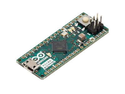
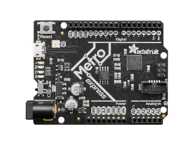
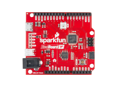
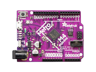
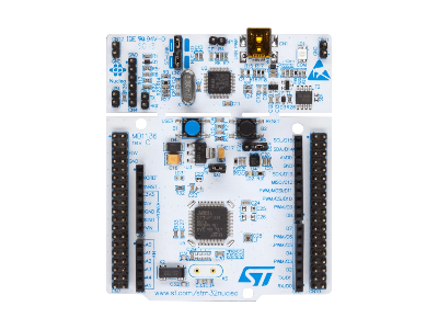
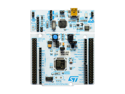
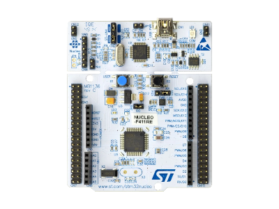
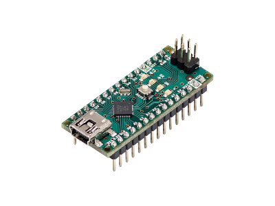
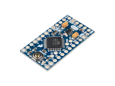
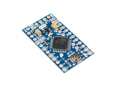
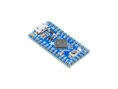
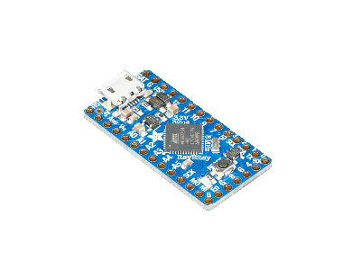
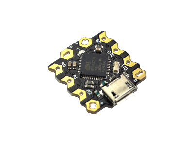
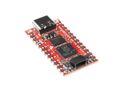
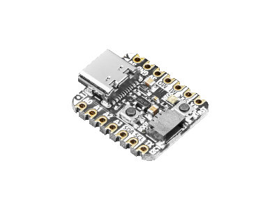
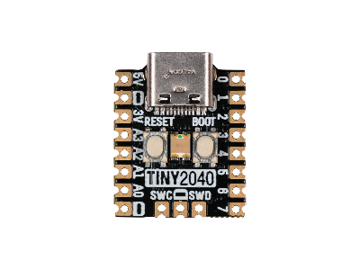
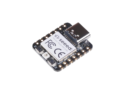
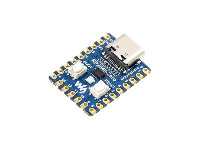
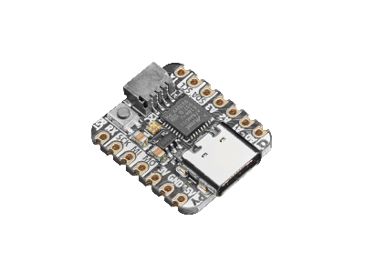
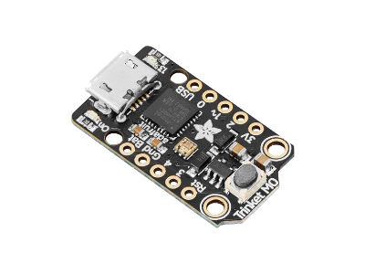
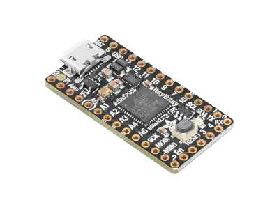
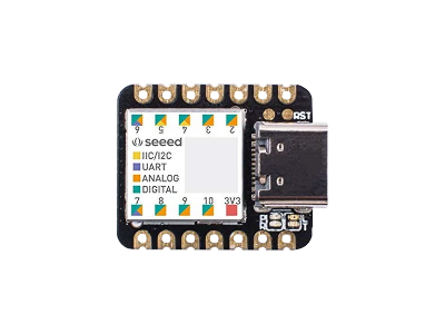
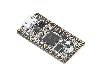
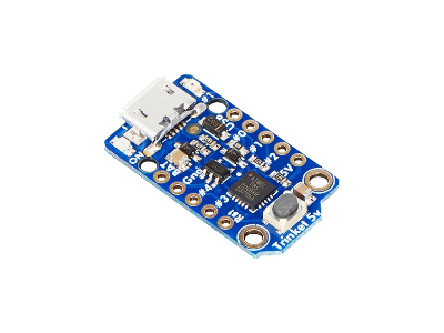
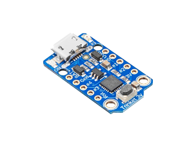
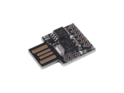
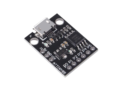
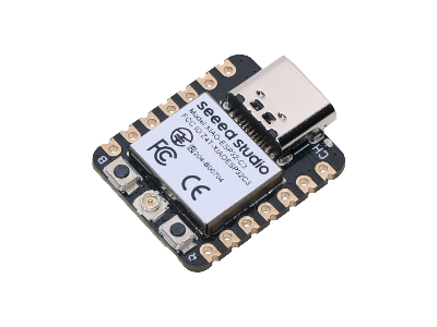
- For small form factor, the ATtiny85, Tiny2040, Seeed Studio XIAO, Adafruit QT Py, or DFRobot Beetle boards are about the size of a postage stamp or smaller.





(0) Comments
Sign in to leave a comment
Sign In