Electronic Data Communication Overview
Updated: 11Aug2024 06:28:16 UTC 2024-08-11T06:28:16Z
Rating: (0 reviewsThis article has not been rated yet)
Electronic data communication involves transferring information (data, text, audio, images, or video) between two or more wired or wireless devices. This introduction to data communication covers the terms and concepts of data transmission and reception in electronic communication systems, including transmitters, receivers, channels/mediums, communication modes, signals, protocols, and message error handling.
Communication Systems
Communication systems consists of a transmitter, communication channel or medium, and a receiver. A message or data (measurements, text, audio, and/or video) is information that is converted into an electronic signal to be sent by the transmitter (TXTransmit) through a channel/medium (wire, free space wireless, or fiber-optic cable) to a receiver (RXReceive) that does what you want with the information (storage, display, or transfer to some other device).
Transmitters & Receivers
In order to send a message it must be converted into an electronic signal that is suitable for transmitting the data over a communication medium. This is the role of the transmitter, which consists of electronic circuitry that changes the voltage levels for a wired transmission or modulates the signal for wireless transmission. Likewise, a receiver consists of electronic circuitry that recovers the transmitted message and converts it into a form that can be used (for storage, display, or transfer to some other device). Transmitters and receivers cover a broad range of electronic devices, from wired devices that use UARTUniversal Asynchronous Receiver-Transmitter, I2CInter-Integrated Circuit. Also referred to as IIC or I2C., SPISerial Peripheral Interface, Ethernet, and USBUniversal Serial Bus to wireless RFRadio Frequency, WiFi, and Bluetooth BTBluetooth devices.
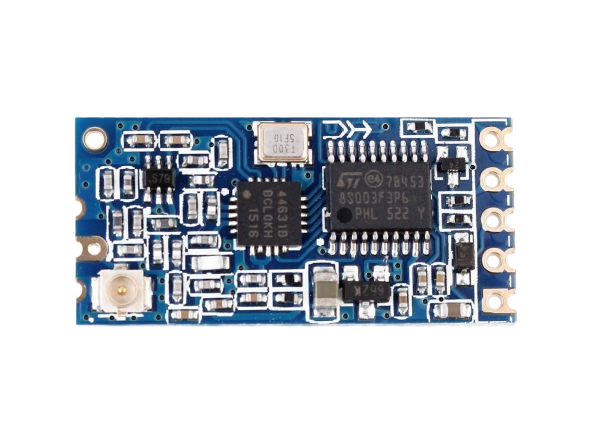
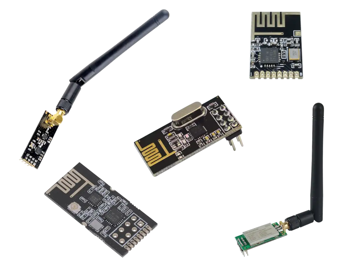
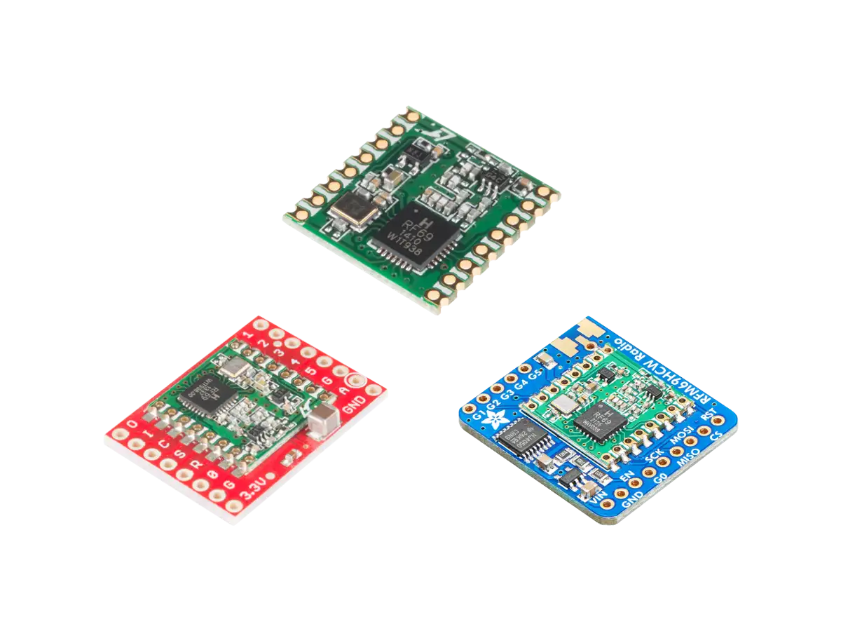
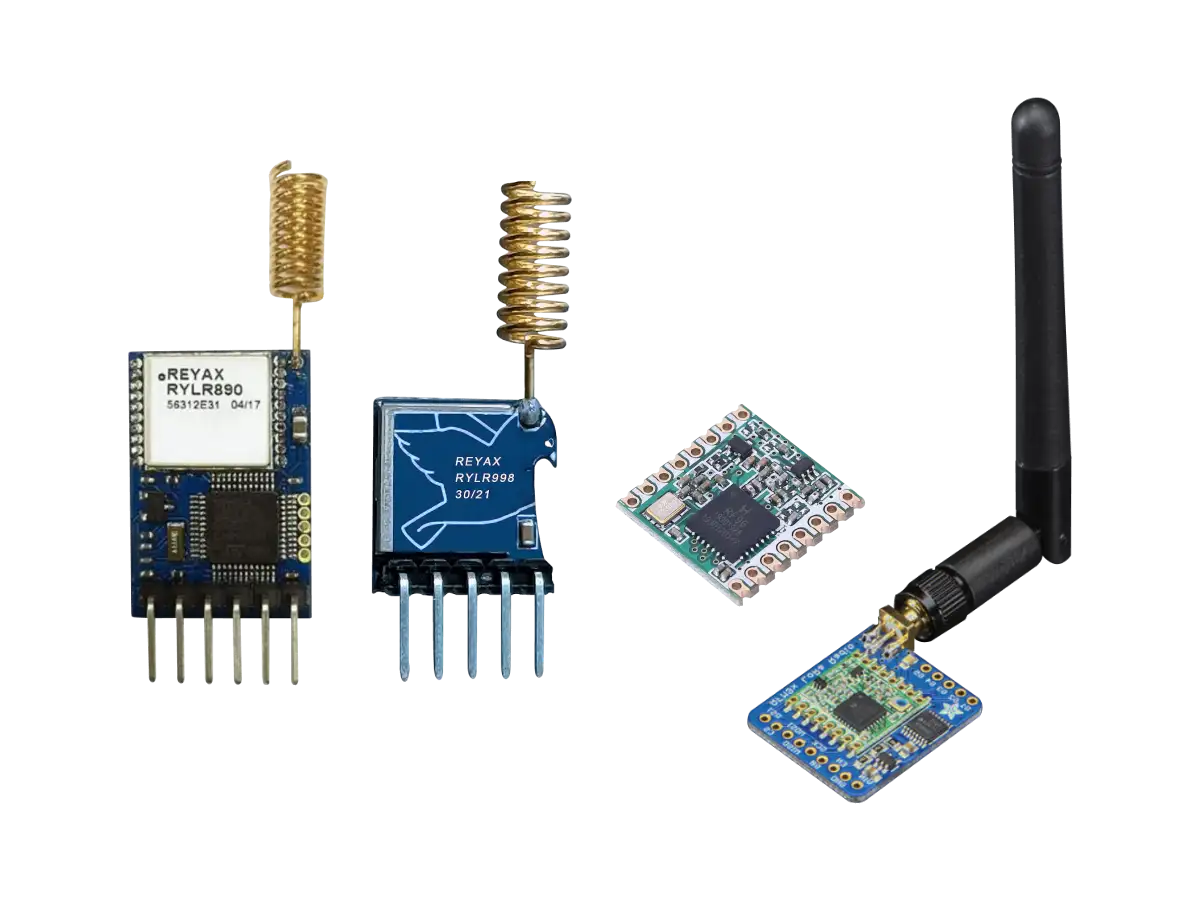
A transceiver combines both the transmitter and receiver in the same device and antenna. One common example is a cellular phone that capable of sending and receiving data. Most RF modules are transceivers, such as the HC-12, nRF24L01+, RFM69, and LoRa, modules. WiFi modules (ESP-01) and WiFi Microcontroller Dev Boards (ESP8266/ESP32 NodMCU boards) are also transceivers.
Communication Channels
The communication channel is the medium by which a signal is sent from one device to another. The medium can be a wire, fiber optic cable, or free space for wireless communication. Wires are conductors that carry an electrical signal. Fiber-optic cables carry information on light waves through the cable and are mainly used for long distance calls and internet connections. Wireless communication makes use of the electromagnetic waves that propagate through free space.
Wires and fiber-optic cables are less prone to electromagnetic interference (EMIElectromagnetic Interference) than wireless, especially if they are shielded (e.g., coaxial cables). Fiber-optic cables are more expensive than electrical conductors and are typically used for industrial applications. However, wires and cables can be costly to install or inconvenient to use compared to wireless.
Types of Communication
Modes
The type of electronic communication mode can be one-way (simplex) or two-way (half-duplex or full-duplex).
- Simplex:
- The communication is unidirectional one-way where only one of the two devices can transmit and the other can only receive. Examples that use the simplex mode of transferring data are a keyboard, mouse, and monitor.
- Half-Duplex or Semi-Duplex:
- Each device can transmit or receive, but not at the same time. When one device is sending, the other device must be receiving. An example that uses half-duplex mode is a Walkie-Talkie where two parties take turns speaking.
- Full-Duplex:
- Each device can transmit and receive at the same time. An example using full-duplex mode is a telephone line where both parties can talk at the same time.
Usage
USB:
USB 2.0 technically only supports half-duplex, although it can switch between In and Out ports fast enough to appear to a human to be full-duplex. The USB 3.0 specification defined a new architecture and protocol, named SuperSpeed (SS), which included a new lane for a new signal coding scheme providing full-duplex data transfers that physically required five additional wires and pins.
Ethernet:
Legacy Ethernet is half-duplex, but full-duplex Ethernet can be achieved using Ethernet switching. Full-duplex Ethernet is used in point-to-point connections between stations and requires that lines be concentrated using Ethernet switches instead of hubs or repeaters. Switched networks employ either a twisted pair or fiber optic cabling that uses separate conductors to provide independent transmit and receive data paths, which avoids collisions and increases throughput.
UART, I2C, and SPI:
For Single Board Computers (SBCSingle Board Computers) and microcontroller boards, wired UARTUniversal Asynchronous Receiver-Transmitter and SPISerial Peripheral Interface support full-duplex communication, whereas I2CInter-Integrated Circuit. Also referred to as IIC or I2C. is inherently half-duplex. However, the full-duplex capability of UART may depend on the specific implementation of the hardware or software, such as having two distinct buffers for storing data.
RF and WiFi Wireless Transceivers:
Most wireless transceivers are half-duplex because full-duplex on the same channel would have an issue with collisions or it would require the use two separate RF channels. The HC-12, nRF24L01+, RFM69, and LoRa RF modules are all half-duplex. WiFi also uses half-duplex communication. The 802.11 protocol is a time division duplex where WiFi devices that act as clients and Access Points (APA WiFi Access Point (AP) is a device that creates a wireless local area network, or WLAN, and acts as a central hub that allows other devices, such as smartphones or computers, to connect to it over WiFi.s) are either in transmit mode or in receive mode. When a WiFi device has some data to transmit, it first checks to see that no other device is transmitting before it transmits data.
Signals
Analog Signals
Analog signals are continuous so they can have an infinite number of different voltages that cover the natural variation of physical phenomenon. The simplest analog signal waveform is the sine wave shown in the figure below (this is a plot of the signal's voltage vs time).
A pure sine wave signal doesn't carry much information. If you were to listen to it in audio it would sound like a flat tone. More variation in the signal's amplitude, frequency, or phase is needed to carry information, such as the audio signal shown in the figure below. The analog audio signal coming from a microphone or output to headphones is a mixture of frequencies in the human audible range of 20Hz to 20,000Hz that varies continuously over time.
Many devices use analog signals, such as audio, video, radio communication, and the output of sensors: any sort of continuous time-varying quantity that conveys the data being collected or transmitted. Sensors can output an analog signal (voltage or current) that varies according to what is sensed. More details about analog signals can be found in the article below.

Created:
12Oct2022 04:27:30 UTC
2022-10-12T04:27:30Z
Updated:
06Aug2024 20:38:51 UTC
2024-08-06T20:38:51Z
Rating: (0 reviewsThis article has not been rated yet)
What is a analog signal? What can you do with a analog signal? This article is an introduction to analog signals covering its usage and wave properties such as DC and AC components, frequency, and bandwidth.
Digital Signals
Binary or logic digital signals have two voltage values: usually one near the reference voltage (ground or zero volts) and the other at the positive I/OInput/Output supply voltage. The ground voltage is represented by binary digit bit 0 and the supply voltage is represented by the binary digit bit 1.
Digital signals can be pulses from a sensor/meter or represent information like numbers, text, audio, images, and video. The transmission of digital signals are more resilient to noise and interference than analog signals, and transmission errors can be detected and corrected. Digital data can also be encrypted, compressed, stored in memory, and edited. More details about digital signals can be found in the article below.

Created:
19Mar2023 00:09:37 UTC
2023-03-19T00:09:37Z
Updated:
06Aug2024 03:10:58 UTC
2024-08-06T03:10:58Z
Rating: (0 reviewsThis article has not been rated yet)
What is a Digital Signal? What can you do with a digital signal? This article is an introduction to digital signals covering its usage and properties of the waveform, bit ordering, voltage level encoding, and timing.
Protocols
When a transmitter sends data it needs to be understandable to the receiver in order to process the data. This is accomplished with a communication protocol, a set of rules that define the syntax, semantics, synchronization, authentication, and may also include error detection. There are many properties of a transmission that a protocol can define with a few given below.
- Identifying the start and end of the message
- Transmission speed
- Handshaking and synchronization
- Message (packet) size
- Address mapping
- Acknowledgment processes
- Error detection and handling
There are thousands of communications protocols that are used in analog and digital communications. Wired connections such as USBUniversal Serial Bus, Ethernet, UARTUniversal Asynchronous Receiver-Transmitter, I2CInter-Integrated Circuit. Also referred to as IIC or I2C., and SPISerial Peripheral Interface all have their own unique protocols. Wireless connections such as WiFi and networks have HTTPHypertext Transfer Protocol, TCPTransmission Control Protocol, UDPUser Datagram Protocol, IPInternet Protocol, and many more protocols for transferring data, as well as security protocols such as HTTPSHypertext Transfer Protocol Secure, SSLSecure Sockets Layer, and TLSTransport Layer Security.
Error Handling
Communication errors could arise from noise in the transmitting or receiving electronics, clock skew, or interference (EMIElectromagnetic Interference) from the transmission medium environment. It is important that any errors in transmission are detected to prevent miscommunication. If an error is detected on the receiver end, then it can request that the message be resent (known as Backward Error Correction BECBackward Error Correction) or perform some kind of auto-recover to correct some kind of errors in corrupted data (Forward Error Correction FECForward Error Correction).
There are many different ways to detect transmission errors to verify data integrity. The general approach is to add some redundancy (some extra data) to the message to be sent that the receiver can use to check its consistency. A common method for verifying data is generating a checksum, a small-sized block of data derived from the message.
Parity Check
A simple checksum algorithm is a parity check, which splits the data into words with a fixed number of n bits, then determines if there is an even or odd number of ones for each word's binary sequence, and appends this parity bit to the end of each word. The transmitter and receiver need to agree on how to interpret the parity bit result of 0 or 1. The most common is an even parity bit, which is 0 if there is an even number of ones and 1 if there is an odd number ones. An odd parity bit is 1 if there is an even number of ones and 0 if there is an odd number ones.
One major limitation with the parity check is that it cannot detect an even number of errors (bits flipped) in the binary sequence. It also cannot detect inserting or deleting bits that are zero.
CRC
A more thorough checksum algorithm would output a unique value for any kind of change in the input message. This is addressed by additionally considering the position of bits in a sequence at a cost of more computing. One common checksum algorithm used in practice is the Cyclic Redundancy Check (CRCCyclic Redundancy Check), which converts the message into a polynomial, divides it by a so-called generator polynomial, and takes the integer remainder of the division as the CRC. If the remainder is zero, the data is assumed to be error-free; otherwise, an error is detected.
There are three common types of CRCs based on their bit length: CRC-16, CRC-32, and CRC-64.
- CRC-16:
- A 16-bit CRC used in many applications, such as Ethernet, WiFi, storage devices, and embedded systems.
- CRC-32:
- A 32-bit CRC used in some file systems, network protocols, data storage, and encryption.
- CRC-64:
- A 64-bit CRC used in high-reliability applications.
CRCs are often used because they are relatively simple to implement in software and hardware, easy to compute mathematically, have a fixed length check value, and are good at detecting common errors that are caused by noise.
Usage
Wired UARTUniversal Asynchronous Receiver-Transmitter communication provides an optional parity bit that can be included in its data packets, but I2CInter-Integrated Circuit. Also referred to as IIC or I2C. and SPISerial Peripheral Interface does not provide any means of error checking. I2C was originally intended to communicate between components on a single board where the probability of error is very low. Also, I2C and SPI are aimed for low power devices with small instruction sets and limited program memory.
WiFi has a Frame Check Sequence (FCSFrame Check Sequence) at the end of each data frame with a CRCCyclic Redundancy Check for error detection and built-in Forward Error Correction (FECForward Error Correction), the process of adding redundant data such as Error Correction Code (ECCError Correction Code) to a message so that it can be recovered by a receiver when errors are introduced. This redundancy allows the receiver to detect a limited number of errors that may occur anywhere in the message, and often to correct these errors without retransmission.
RFRadio Frequency modules vary in their built-in capability of any error detection and correction. For example, the HC-12 RF module only has the built-in capability of appending a parity bit to the message for error detection, but you have to implement the algorithm to compute the parity bit in the software that sends the message, and there is no built-in error correction. However, the nRF24L01+ RF module has built-in hardware CRCCyclic Redundancy Check error detection, error correction, and resending. If an RF module does not have any built-in error detection, you can compute your own checksum of the message, like a CRC, and add it to the end of the message. You can also add your own error correction algorithm and auto resend in software.
Conclusion
This article covered some basic terminology and concepts of data transmission and reception in electronic communication systems, such as the components (transmitter, receiver, and transceiver), channel mediums, types (simplex, half-duplex, and full-duplex), digital and analog signals, protocols, and error handling.
This was a general overview of data communication that is common to both wired and wireless channels. The transmission method, encoding, data rate, bandwidth, and transmitting/receiving levels depend on the type of channel (medium) used. Both wired and wireless communication are explored in more depth in the articles referenced in the Related Content section below.
Related Content
More details about wired communication, such as serial transmission, encodings, bit patterns, and wiring can be found in the wired communication listings below.


More details on wireless communication, such as frequency bands, channels, bandwidth, modulation, air data rate, range, receiving sensitivity, and transmitting power can be found in the wireless communication listings below.


(0) Comments
Sign in to leave a comment
Sign In