Electronic Wired Communication Overview
Updated: 11Aug2024 08:33:17 UTC 2024-08-11T08:33:17Z
Rating: (0 reviewsThis article has not been rated yet)
Electronic wired communication involves transferring information (data, text, audio, images, or video) over wires between two or more devices. This overview of wired communication covers the terminology and concepts of data transmission and reception in electronic communication systems. The different types signals used for data transmission and common examples of wired communication are covered.
Analog Data Transmission
Analog data transmission is a method of conveying information using a continuous signal that varies in amplitude, frequency, or phase, in proportion to that information. Audio and video are briefly discussed in the following subsections as examples of analog data transmission, although any information may be conveyed by an analog signal as a response to changes in a physical variable, such as light, temperature, pressure, position, and much more.
Audio
The analog audio signal coming from a microphone or output to headphones is a mixture of frequencies in the human audible range of 20Hz to 20,000Hz that varies continuously over time.
The output of an electret microphone is usually in the millivolt range if not amplified. Breakout board microphones often come with a pre-amplifier built in so it is compatible with the range and resolution of an ADCAnalog-to-Digital Converter (ADC, A/D, or A-to-D) in a sound card for a computer and in microcontroller boards. A microphone takes in a mic level signal (millivolts), amplifies it, and outputs a line level signal (around 1 Volt). A line level is the specified strength of an audio signal used to transmit analog audio between devices. Consumer electronic audio devices (e.g., sound cards) often have a connector labeled Line In and/or Line Out, where Line Out provides an audio signal output and Line In receives a signal input.
Video
Analog video signals used for TV formats such as NTSCNational Television System Committee (North America), PALPhase Alternating Line (Europe), and SECAMSequential Color with Memory (Africa, Middle East, and other regions), involve a mixture of time-division multiplexing (sync and video information) and frequency-division multiplexing (luminance, chroma, and sound).
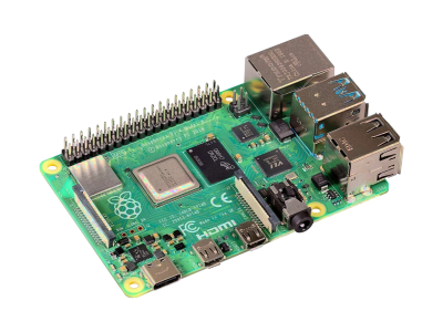
Multiplexing is the process of simultaneously transmitting two or more individual signals over a single communication channel, which is how only a 1 wire yellow RCARadio Corporation of America line (signal and ground) can make a whole color TV image appear on a screen full of thousands of pixels. The composite video coming out of an RCA jack is an analog signal usually ranging between 0 and 1.073V, where tiny changes in the signal have a huge effect on the color or location of the video (sound is transferred on separate white and red wires). Some SBCSingle Board Computers, like the Raspberry Pi 4B, have an onboard 3.5mm jack that outputs composite video. A typical signal waveform for one horizontal scan line (row) of an image in composite video is shown in the figure below.
- Front Porch and Back Porch:
- The front porch is a brief pulse (about 1.5μs) to distinguish the sync pulse from its surroundings and allow voltage levels to stabilize in older televisions, preventing interference between picture lines. The back porch is used to restore the black level reference in analog video that compensates for the fall time and settling time following the sync pulse.
- Line Sync Pulses:
- The line sync pulses are a short period of zero volts that fills the time between the picture line in order to keep the display synchronized with the source.
- Color Burst:
- The color burst signal is a pure sine wave that is at the frequency and phase of the color subcarrier, used to keep the chrominance subcarrier synchronized in a color television signal. This allows the reference oscillator in the color decoder circuit to be phase-locked to the one used to encode the color information at the source, ensuring that the reference oscillator never has the time to drift out of phase.
- Picture Information:
- The picture line signal consists of a linear combination of the luminance (brightness) of the picture and a modulated subcarrier which carries the chrominance (color information, hue and saturation). The details of the combining process varies between the NTSC, PAL and SECAM systems. Luminance information is obtained from the voltage levels baseband signal, where higher voltages produce more brightness. Color information is added on top of the luma signal as a sine wave with the colors identified by a specific phase difference between it and the color-burst reference phase. The amplitude of the modulation is proportional to the amount of color (saturation), and the phase provides the tint (hue) of the color.
Digital Data Transmission
The data in a digital transmission is transferred in the form of binary bits (1s and 0s). There are two ways to move binary bits from one device to another: transmit all bits of a word simultaneously (parallel) or send only 1 bit at a time (serial).
Parallel Transmission
Parallel communication is the process of sending multiple data bits simultaneously using several channels (wires), and may have additional wires for other signals, such as a clock signal to pace the flow of data, a signal to control the direction of data flow, and handshaking signals. Parallel communication is often used in integrated circuits for peripheral buses and in memory devices such as RAMRandom Access Memory. Some common examples of parallel communication protocols are ISAIndustry Standard Architecture, PATAParallel Advanced Technology Attachment, SCSISmall Computer System Interface, PCIPeripheral Component Interconnect, IEEEInstitute of Electrical and Electronics Engineers (Industry Standards)-488, and the old IEEE-1248 Parellel Printer Port.
A multiwire cable or multiple traces on a PCBPrinted Circuit Board is used to transfer parallel data. There is one line for each bit of information to be transmitted with all data lines referenced to a common ground. Multiple parallel lines that carry digital data are usually referred to as a data bus. Parallel data transmission is fast because all the bits of data word are transferred simultaneously. The transfer speed can as fast as a few nanoseconds, but depends on the propagation delay in the transmitting and receiving logic circuits and any time delays from the bus lines (the capacitance and inductance in the bus lines and crosstalk between the lines limits the speed).
Serial Transmission
Serial communication is the process of sending data one bit at a time, sequentially, over a channel. There are many different types of serial communication such as USBUniversal Serial Bus, Ethernet, PCIePeripheral Component Interconnect Express, CANController Area Network (CAN) is a high-integrity serial communication bus designed for harsh environments such as industrial and automotive applications., UARTUniversal Asynchronous Receiver-Transmitter, I2CInter-Integrated Circuit. Also referred to as IIC or I2C., SPISerial Peripheral Interface, 1-Wire, RSRecommended Standard232, SATASerial Advanced Technology Attachment, etc.
Synchronization between the transmitter and receiver must be maintained to allow both to be expecting transmission/reception at the same time. There are two different ways of maintaining synchronization.
- Synchronous Communication:
- Data sent in a continuous stream using a separate line with a pulsed clock signal for synchronization. Data bits are sent and received on the rising or falling edge of the common clock's signal. Examples of synchronous communication are I2CInter-Integrated Circuit. Also referred to as IIC or I2C. and SPISerial Peripheral Interface.
- Asynchronous Communication:
- There is no clock line, where data is sent in the form of packets with start and stop bits added with both the transmitter and receiver configured to the same baud rate. Data can be sent intermittently rather than a steady stream. Examples of asynchronous communication are UARTUniversal Asynchronous Receiver-Transmitter and RS232.
Although a serial data transfer may seem inferior to a parallel transmission because it transmits less data per clock cycle, it is often the case that serial can be clocked considerably faster than parallel in order to achieve a higher data rate.
Transmission Rates
The data transfer speed of serial transmissions is usually indicated by the value of the bit rate or the baud rate.
- Bit Rate:
- The bit rate is the number of bits that occur in a given unit of time, expressed as bits per second (bpsbits per second or bit/s). You may also see the bit rate expressed as bytes per second (B/s), which corresponds to 8bit/s. The bit rate is the reciprocal of the bit interval t, or bps = 1/t. For example, if the bit time is 104.17μs, the bit rate is bps = 1/104.17μs = 9600bpsbits per second.
- Baud Rate:
- The baud rate is the number of signaling elements or symbols that occur in a given unit of time. This symbol rate is measured in baud (Bd) or "symbols per second". The signaling element or symbols is some change in the binary signal, where each symbol may encode one or several binary digits (bits). If the system has only 2 symbols (on/off or high/low) transferred, then the baud is equivalent to bits per second (bpsbits per second). For example, 9600 baud means that data is being transferred at 9600 bits per second. In general, the bit rate is related to the baud rate by the equation in the figure below.
USB
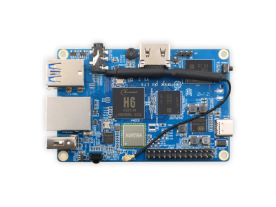
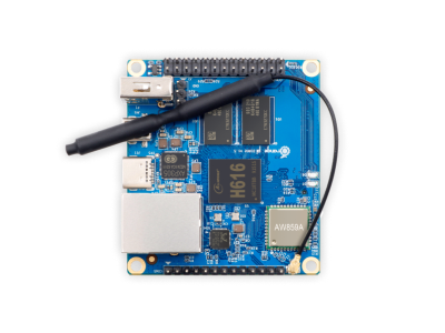
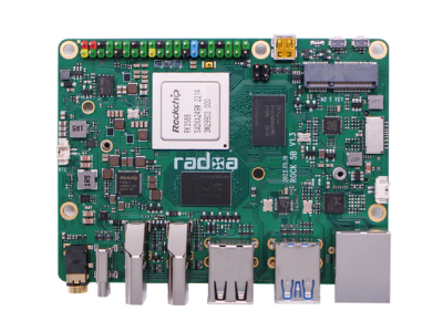
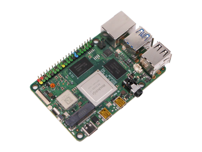
USBUniversal Serial Bus ports are standard on all computers in order to connect peripherals such as a keyboard and mouse. The most common USB connectors on SBCSingle Board Computers are female Type-A, Micro-B, and Type-C. USB ports are also found on many microcontroller boards for programming, communicating, and power. Microcontrollers typically have smaller versions of USB connectors, such the Micro-B and Type-C.
There are different versions of USB that that determine the maximum data transfer rate and cable length (the maximum cable length depends on the USB speed) listed in the table below. These are all the USB versions commonly found in SBCs, where microcontroller boards typically have USB 2.0 or lower. There are higher USB versions (e.g., USB 3.2, USB4, and USB4 V2.0) available for modern desktop and laptop computers, but are typically not implemented in SBCs and microcontroller boards yet as of this writing.
| SBC | Max Data Rate | Max Cable Length |
|---|---|---|
| USB 1.0 | Low-Speed: 1.5 MbpsMegabits per second | 3m (9.8ft) |
| USB 1.1 | Full-Speed: 12 MbpsMegabits per second | 5m (16.4ft) |
| USB 2.0 | High-Speed: 480 MbpsMegabits per second | 10m (32.8ft) |
| USB 3.0 | SuperSpeed: 5 GbpsGigabits per second | 5m (16.4ft) |
| USB 3.1 | SuperSpeed: 10 GbpsGigabits per second | 5m (16.4ft) |
When connecting devices with different USB versions, the data transfer rate will be limited by the slowest of the connected devices. For example, if you connect a High-Speed USB 2.0 device to a Low-Speed USB 1.1 device, the data transfer will be Low-Speed.
Some SBCs offer USB On-The-Go (OTGUSB On-The-Go (OTG) is a specification built into the USB port that allows devices to act as a host to control and power external devices or act as a peripheral.) ports, which is a specification built into the USB port that allows devices to act as a host to control and power external devices or act as a peripheral. SBCs with USB OTG can switch back and forth between the roles of host and device, where it can be a host to peripherals such as a mouse and keyboard or be seen as a device by host computer.
Ethernet
An Ethernet port is a hardware interface that connects a computer to a network. Ethernet is capable of transmitting large amounts of data at high speed, can accommodate multiple transmission data rates, and provides a stronger signal over a longer distance compared with a USBUniversal Serial Bus cable (e.g., Cat5, Cat5e, and Cat6 Ethernet cables can go up to 100m/328ft in length before signal attenuation occurs). Ethernet can be used to connect to the Internet, a Local Area Network (LANLocal Area Network), or a Wide Area Network (WANWide Area Network). You can also use Ethernet to connect an SBC to video cameras or to your home modem/router to monitor internet speeds.
Ethernet ports come in different speeds with the two most common speed standards for computers being 10/100 and 10/100/1000 developed by the Institute of Electrical and Electronics Engineers (IEEEInstitute of Electrical and Electronics Engineers (Industry Standards)). A 10/100 Ethernet connection is capable of transferring data at either 10MbpsMegabits per second or 100MbpsMegabits per second. A 10/100/1000 Ethernet, also referred to as Gigabit Ethernet or GbEGigabit Ethernet (GbE) provides a data rate of 1 billion bits per second., is capable of transferring data at either 10MbpsMegabits per second, 100MbpsMegabits per second, or 1000MbpsMegabits per second (1GbpsGigabits per second). The speed of an Ethernet port is determined by the Ethernet controller ICIntegrated Circuit, Ethernet connector, and the type of cable that is used. Ethernet cables are separated into categories (Cat) determined by how much bandwidth it can handle with all of the cable categories remaining backward compatible. For instance, Cat5 supports up to 100MbpsMegabits per second, while Cat5e and Cat6 support up to 1GbpsGigabits per second.
GPIO Communication Ports
Most SBCSingle Board Computers and microcontroller boards with a GPIO header have UARTUniversal Asynchronous Receiver-Transmitter, I2CInter-Integrated Circuit. Also referred to as IIC or I2C., and SPISerial Peripheral Interface serial communication ports intended for small amounts of data transfer over a short distance. These three will be covered in the following subsections, but there are many other types of serial communication protocols such as CANController Area Network (CAN) is a high-integrity serial communication bus designed for harsh environments such as industrial and automotive applications., 1-Wire, Microwire, RSRecommended Standard232, RSRecommended Standard422, RSRecommended Standard485, SATASerial Advanced Technology Attachment, SMBusSystem Management Bus, etc (many I2C devices can work on an SMBus, but some SMBus protocols add semantics beyond what is required to achieve I2C branding).
UART
The Universal Asynchronous Receiver Transmitter (UARTUniversal Asynchronous Receiver-Transmitter) uses two data lines, one to transmit (TXTransmit) and another to receive (RXReceive), for half-duplex or full-duplex communication.
- TXTransmit:
- output transmitting data
- RXReceive:
- input receiving data
Since UARTUniversal Asynchronous Receiver-Transmitter is asynchronous and has no clock signal line, the transmission data must have bits that indicate the start and end of the message. Data is sent over the bus in the form of a packet, which consists of a start bit, data frame (5 to 9 bits), a parity bit, and stop bits. Also, both devices must configured to operate at the same baud rate. The user must select a baud rate from a set of possible rates on the devices because they depend on the system clock, but are generally within the range of 9600bpsbits per second and 115,200bps (the maximum limit of UART is 5MbpsMegabits per second).
I2C
Inter-Integrated Circuit (I2CInter-Integrated Circuit. Also referred to as IIC or I2C.) is a synchronous bus that uses two wires, a Serial Line Clock (SCLSerial Clock (SCL) is the output clock signal line from the master device. Also referred to as SCK, SCLK, or CLK.) and Serial Data Line (SDLSerial Data Line), for half-duplex communication over a short distance. I2CInter-Integrated Circuit. Also referred to as IIC or I2C. is also referred to as a Two-Wire Interface (TWITwo-Wire Interface). It operates on the master-slave principle with the master as the main controller and peripheral devices as the slaves.
- SDL (Serial Data Line):
- used by the master or slave to transmit/receive data
- SCL (Serial Line Clock):
- used by the master to transmit the clock signal
Both the SDASerial Data Line and SCLSerial Clock (SCL) is the output clock signal line from the master device. Also referred to as SCK, SCLK, or CLK. lines have pull-up resistors (RPU) that are pulled up to VDDVoltage Drain Drain (VDD) is the supply voltage at the Drain of a transistor. The double subscript notation of repeating letters "DD" is used to denote a power supply voltage that is relative to ground. , the logic level supply of the master device. The I2CInter-Integrated Circuit. Also referred to as IIC or I2C. bus drivers are open drain drivers, which means they can drive drive their output low, but cannot drive it high. For the line to be able to go high there has to be pull-up resistors to VDDVoltage Drain Drain (VDD) is the supply voltage at the Drain of a transistor. The double subscript notation of repeating letters "DD" is used to denote a power supply voltage that is relative to ground. . Some devices already have pull-up resistors within them for the SDASerial Data Line and SCLSerial Clock (SCL) is the output clock signal line from the master device. Also referred to as SCK, SCLK, or CLK. pins, where external pull-up resistors are not needed.
The original I2C bus had a maximum speed of 100kHz, now called the standard mode. Most applications still use this speed, since it is usually sufficient for transferring data with most modules, such as sensors, memory modules, and LCDLiquid Crystal Display displays. The I2C protocol specifies this standard mode and higher speed modes, as given in the table below, but not all I2C devices support these modes.
| Mode | Speed |
|---|---|
| Standard Mode (Sm) | 100kbps |
| Fast Mode (Fm) | 400kbps |
| Fast Mode Plus (Fm+) | 1Mbsp |
| High-Speed Mode (Hs) | 3.4Mbps |
| Ultra-Fast Mode (UFm) | 5Mbps |
One of the main advantages of I2CInter-Integrated Circuit. Also referred to as IIC or I2C. is the capability of adding as many peripheral devices as you want to the bus (SDASerial Data Line and SCLSerial Clock (SCL) is the output clock signal line from the master device. Also referred to as SCK, SCLK, or CLK. lines) as long as the maximum bus capacitance of 400pF is not exceeded. This is illustrated in the figure below.
SPI
The Serial Peripheral Interface (SPISerial Peripheral Interface) provides synchronous full-duplex communication on the master-slave principle using four lines.
- MOSI (Master Out, Slave In):
- used by the master to transmit data to the slave
- MISO (Master In, Slave Out):
- used by the slave to transmit data to the master
- SCLK (System Clock):
- used by the master to transmit the clock signal. Also referred to as SCK, SCL or CLK.
- SS (Slave Select):
- used by the master to select a slave
SPISerial Peripheral Interface operates on the master-slave principle with the master as the main controller and peripheral devices as the slaves. Two different wiring configuration can be used for multiple slave devices: the independent slave configuration and daisy chain slave configuration.
In the independent slave configuration, the master uses different SSSlave Select (SS) is the SPI output line from the master device to indicate that data is being sent. Also referred to as Chip Select (CS). lines for each slave device shown in the figure below. When the master wants to communicate with a particular slave, it pulls its SSSlave Select (SS) is the SPI output line from the master device to indicate that data is being sent. Also referred to as Chip Select (CS). state LOW during the duration of the communication exchange.
In the daisy chain slave configuration, the master uses only one SSSlave Select (SS) is the SPI output line from the master device to indicate that data is being sent. Also referred to as Chip Select (CS). line connected to all the slave devices shown in the figure below. When the master wants to communicate with a particular slave, it pulls its SSSlave Select (SS) is the SPI output line from the master device to indicate that data is being sent. Also referred to as Chip Select (CS). state LOW to initiate communication, sends data over its MOSIMaster Out Slave In (MOSI) is the SPI data output line from the master device to the first slave device in the chain, which then flows from one slave to the next in the chain.
SPISerial Peripheral Interface is the fastest protocol compared to UARTUniversal Asynchronous Receiver-Transmitter and I2CInter-Integrated Circuit. Also referred to as IIC or I2C.. Communication speeds depend on the clock frequency of the master device using a frequency supported by slaves devices, which are typically up to a few MHz.
Conclusion
This overview of wired electronic communication covered analog and digital signals used for data transmission and some common examples of wired communication. USB and Ethernet offer the highest data transfer rates on the order of GbpsGigabits per second for exchanging a lot of data. Wired UART, I2C, and SPI serial communication ports on the GPIO header of most SBCs and microcontroller boards are intended for small amounts of data transfer over a short distance and have a simpler hardware interface and software control. UART is the slowest while SPI is the fastest, but this comes the expense of needing more wires to connect devices.




(0) Comments
Sign in to leave a comment
Sign In