UART Communication
Updated: 11Aug2024 22:51:42 UTC 2024-08-11T22:51:42Z
Rating: (0 reviewsThis article has not been rated yet)
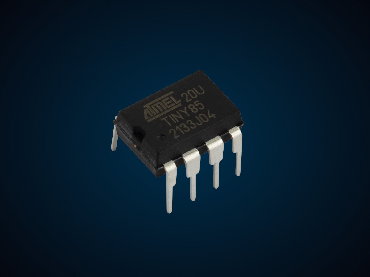
A Universal Asynchronous Receiver-Transmitter (UARTUniversal Asynchronous Receiver-Transmitter) is one of the most common and simplest ways to have bidirectional data communication between devices. UART is not just a communication protocol like SPISerial Peripheral Interface and I2CInter-Integrated Circuit. Also referred to as IIC or I2C., but a physical circuit in a microcontroller, SBCSingle Board Computer, or a stand-alone ICIntegrated Circuit that consists of a clock generator, shift registers, buffers, and control logic.
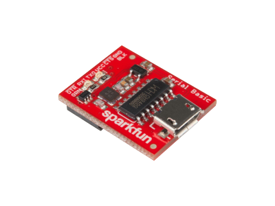
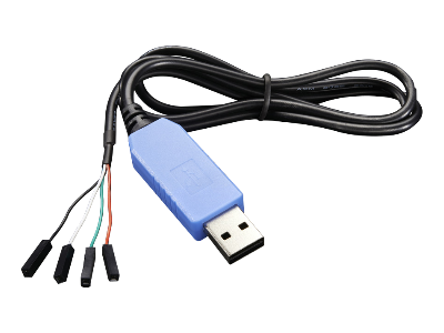
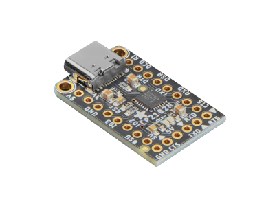
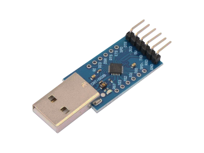
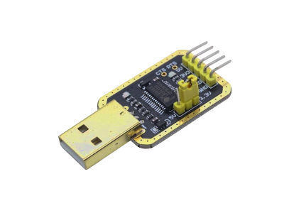
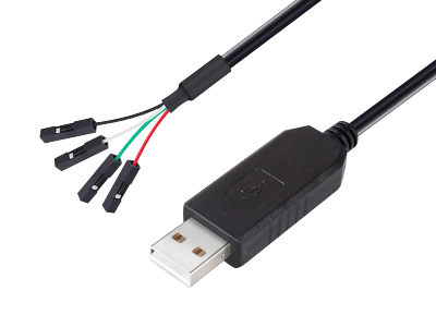
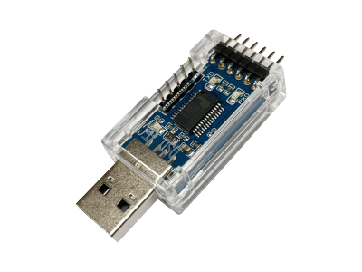
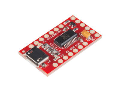
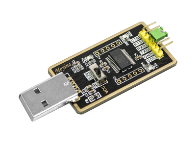
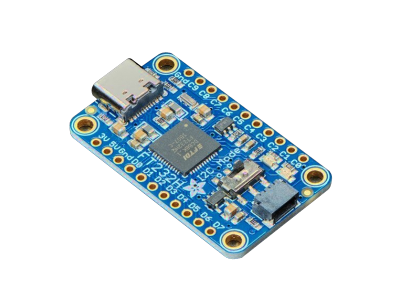
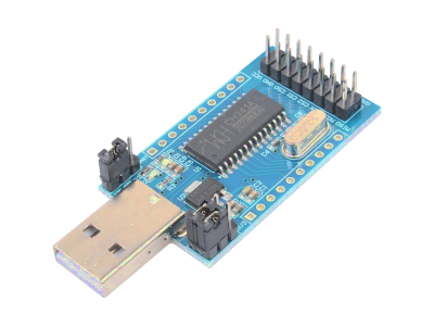
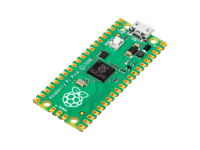
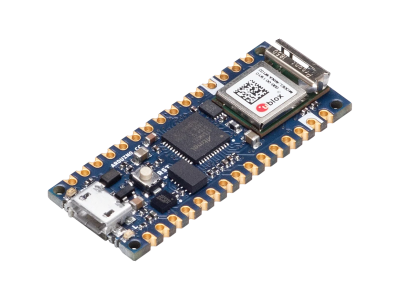
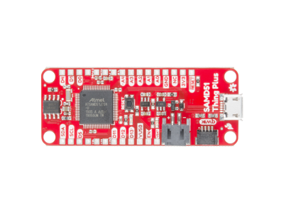
USBUniversal Serial Bus Serial Adapters use UART hardware for exchanging data with a computer console. Many sensors and other modules use UART for control and transferring data. Most SBCs and microcontroller boards have one or more UART ports, where the user can interface the hardware wiring and control the flow of data with software.
This introduction to UART will cover its hardware wiring, data transmission, signals, speed, and software UART.
Hardware Wiring
UART uses two data lines, one to transmit (TXTransmit) and another to receive (RXReceive), and a common ground line. The (TX, RX) data lines can support half-duplex or full-duplex communication depending on the hardware. There could also be a power line in order to supply power from one of the devices to the other or each device may have its own power source.
- TXTransmit:
- output transmitting data
- RXReceive:
- input receiving data
- GNDCommon Ground:
- common ground
- VDDVoltage Drain Drain (VDD) is the supply voltage at the Drain of a transistor. The double subscript notation of repeating letters "DD" is used to denote a power supply voltage that is relative to ground. :
- (optional) power supply line
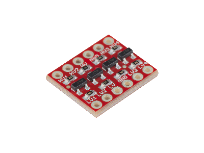
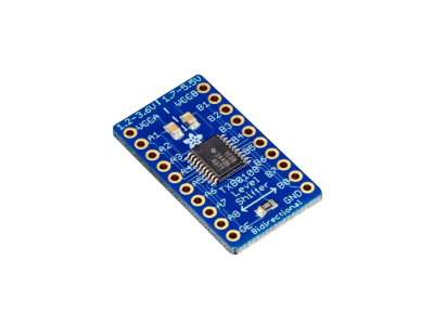
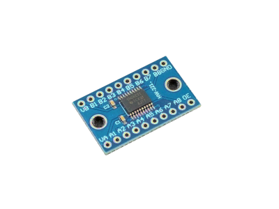
Both devices should have the same (TX, RX) signal voltage level (e.g., 3.3V to 3.3V or 5V to 5V). If the devices are at different voltage levels, a voltage level shifter circuit needs to be added externally between the devices to make them compatible.
Data Packets
UART communication is asynchronous, which means the signals are not synchronized using a common clock signal line. UART signals are synchronized by transmitting data bits to indicate the start and end of the message and both devices must be configured to operate at the same baud rate. The transmitter sends data bits one by one, framed by start and stop bits, and the receiver samples the incoming data using its internal clock signal.
Data is sent over the bus in the form of a packet or frame, which consists of a start bit (1 bit), data bits (5 to 9 bits), parity bit (0 to 1 bit), and stop bits (1 to 2 bits). Both the baud rate and the number of bits in the data, parity, and stop bits are specified in the software configuration of both devices before using UART.
Start Bit
The start bit indicates the beginning of a packet sent and is used is used to synchronize the transmitter and receiver. UART is normally held HIGH in its idle state before transmitting data. The start bit is LOW, so a HIGH-to-LOW transition indicates the beginning of each data packet/frame. The data bits then follows the start bit.
Data
The data bits contain the actual message contents of the transmission. The length of this data can be anywhere from 5-bits up to 8-bits if a parity bit is used or up to 9-bits if a parity bit is not used (it is usually set to 8-bits). Before using UART you must configure the number of data bits in software of both devices, so UART knows where the end of the data bits in a packet are and the start of either the parity or stop bits.
Parity
The optional parity bit is a way for the receiver to detect any errors (corrupted data) that occurred during the transmission. Message errors may be caused by noise in the electronics of the devices, clock skew (mismatched baud rates), or interference in the wires.
Including this parity bit will slightly slow down the data transfer and requires some implementation of error handling on both sender and receiver (usually, received data that fails must be re-sent). The parity bit is optional, so you don't have to include the bit in the packet.
The parity check determines if there is an even or odd number of ones in the data binary sequence, and and uses a single bit to represent even/odd. The transmitter and receiver need to agree on how to interpret the parity bit result of 0 or 1. The most common is an even parity bit, which is 0 if there is an even number of ones and 1 if there is an odd number ones. An odd parity bit is 1 if there is an even number of ones and 0 if there is an odd number ones.
One major limitation with this type of error checking is that it cannot detect an even number of errors (bits flipped) in the binary sequence. It also cannot detect inserting or deleting bits that are zero. A more thorough checksum algorithm would output a unique value for any kind of change in the input message, such as a CRCCyclic Redundancy Check.
Stop Bits
The stop bit indicates the end of the packet/frame transmission with a HIGH logic level (the same as the idle state of the signal). There can be one or two stop bits set in the software configuration. Normally one stop bit is used, but having two stop bits can be a useful way to add extra receiving processing time, especially at high baud rates, where more time is needed to process the packet bits.
Bit Ordering
The order in which the bits are transmitted over a communication channel is called Endianness. There are two types of endianness. Little-endian has the Least Significant Bit (LSBThe Least Significant Bit (LSB) in a binary number is the bit that represents the smallest place value carrying the lowest weight. It is also sometimes referred to as the low-order bit or right-most bit due to the convention in positional notation of writing less significant digits further to the right.) sent first and Most Significant Bit (MSBThe Most Significant Bit (MSB) in a binary number is the bit that represents the largest place value carrying the most weight. It is also sometimes referred to as the high-order bit or left-most bit due to the convention in positional notation of writing less significant digits further to the right.) sent last. Big-endian transmits the MSB first and the LSB last.
For example, suppose we want to send the number 45 serially over a transmission line. The number 45 is 00101101 in binary. Big-endian bit ordering would be transmitted left to right (00101101) and little-endian would be transmitted right to left (10110100). The endianness of a UART transmission depends on the devices communicating, but is typically little-endian.
UART Signal
When sending a transmission over UART, both devices should have the same (TX, RX) signal voltage level (e.g., 3.3V to 3.3V or 5V to 5V). If the devices output signals at different voltage levels, a voltage level shifter circuit needs to be added externally between the devices to make them compatible.
A resistor divider only drops the voltage one way and the extra resistance limits the data rate by slowing down the rise time of the signal, so a BSS138 FETField Effect Transistor Logic Level Converter or a buffer/driver level shifter ICIntegrated Circuit is recommended (a list of options is provided in the purchase section).
When UART is not transmitting data, called an idle state, the line is normally held HIGH. The start bit of the packet/frame indicates the beginning of the transmission in a LOW state, then data bits ordered from LSB to MSB are transferred, an optional parity bit, and finally a HIGH stop bit ends the packet. After the transmission, the signal level is brought back to the idle state HIGH level before sending another transmission.
An example of a UART signal with a packet containing the number 45, which is 00101101 in binary, is shown in the figure below. The HIGH voltage level of the signal is shown as 3.3V or 5V, which are common voltages on microcontrollers and SBCSingle Board Computers, but can be a different voltage depending on the devices used. The LOW voltage level of 0V is referenced to ground.
Transmission Speed
The baud rate specifies how fast data is transferred over a serial line and is usually expressed in units of bits-per-second (bpsbits per second). The higher a baud rate (bps), the faster data is sent/received.
If you invert the baud rate, you can find out just how long it takes to transmit a single bit, which is the same as how long the transmitter holds a serial line HIGH/LOW and at what period the receiving device samples its line. For example, if the baud rate is 9600bps, it means that 9600 bits are transferred over the line each second with a bit time interval of approximately 104μs.
The devices that communicate over UART must be configured to operate at the same baud rate. The user typically selects a baud rate from a set of possible rates on the devices because they depend on the system clock, but are generally within the range of 9600bps and 115200bps.
The maximum limit of UART is 5Mbps, but you usually will not see speeds exceeding 115200bps on most microcontrollers or other embedded processors because the clock and sampling period cannot keep up. If the baud rate is too high, more than the devices can handle, then errors will creep into the transmission.
Software UART
If a device such as a microcontroller or SBC doesn't have a UART port or enough of them for your application, then the digital I/OInput/Output pins can be controlled by the processor to emulate UART (a technique known as Bit Banging).
There are libraries available, like the Arduino SoftwareSerial Library, that make this more convenient for serial interfaces. Bit-banging is more processor-intensive, not as reliable, and not as fast as hardware UART, but it can be useful when needed.
One common situation where a software UART would be used is when you're trying to hookup a UART module (e.g., sensor) to a microcontroller board and want to display the data on a computer, but the microcontroller board has only one UART port that is shared by the USB port.
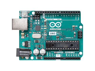
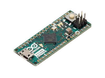
This is the case with the Arduino Uno R3 and Nano boards where the UART header pins (RX0, TX1) are physically connected to a USB-to-UART converter circuit for USB communication, which means you cannot use the (RX0, TX1) pins if you are already using the USB to send/receive data to a computer. Here you can use the SoftwareSerial library that provides the capability of UART communication on other digital pins. There are other Arduino boards (e.g., Arduino Zero, MKR1000, and 101) that have multiple hardware UART interfaces separate from the USB port where they can be used at the same time.
Conclusion
This introduction to UART covered its hardware wiring, data packet structure, bit ordering, signals, transmission speed, and software UART. There are advantages and disadvantages to using UART compared to other wired communication protocols such as I2C and SPI.
Some of the advantages of using UART are:
- Only requires two data lines for transmission without a need for a clock signal line
- Has a simple data packet structure
- The parity bit can provide some low level error checking
Some disadvantages of using UART are:
- The size of the data in a packet/frame is very limited
- The speed is often lower in devices compared to I2C and SPI that can reach up to a few Mbps
- An initial software configuration is needed to set the baud rate and number of bits in the packets
However, UART has been around for a long time and is one of the most common and simplest ways to achieve bidirectional communication between devices.





(0) Comments
Sign in to leave a comment
Sign In