Logic Level Converters
Updated: 26Aug2024 04:58:53 UTC 2024-08-26T04:58:53Z
Rating: (0 reviewsThis article has not been rated yet)
There are circumstances where you need to interface two devices with different I/OInput/Output voltage levels, such as a 3.3V device to a 5V device. This is where you need some external circuitry to perform voltage level shifting/conversion in order to protect the 3.3V device from 5V. The level converter shifts a high voltage signal to a low voltage signal or viceversa.
This overview covers different logic level converters, such as Resistor Voltage Dividers, BSS138 MOSFETMetal-Oxide-Semiconductor Field-Effect Transistor, Logic Level Shifter ICIntegrated Circuits, TXB modules, and TXS modules.
An important factor to consider when choosing a level converter Level converters is the direction of the signal it supports. The two main types are uni-directional and bi-directional converters.
- Uni-Directional:
- Converts voltage in one direction only. The input pins are dedicated to one voltage and the output pins are dedicated to the other voltage. Examples of uni-directional level shifters are resistor dividers, 74AHCT125 IC, and 74VC245 IC.
- Bi-Directional:
- Converts voltage in both directions where the pins can be either input or output. The direction can be from an external signal on a control pin or have auto sensing. Examples of bi-directional level shifters are BSS138 FETField Effect Transistor shifter circuit, TXB series ICs, and TXS series ICs.
Another factor to consider when choosing a level converter is the type output configuration it supports. The two main output configurations are push-pull and open-drain.
- Push-Pull:
- A push-pull output is capable of driving high and low output levels. It can both source and sink current, with a transistor connecting to VCCVoltage Collector Collector (VCC) is the supply voltage at the collector of a transistor. The double subscript notation of repeating letters "CC" is used to denote a power supply voltage that is relative to ground. or GNDCommon Ground to drive a signal high or low. When the output goes low, the signal is actively pulled to ground, and when it goes high, it is actively pushed to VCC. Push-pull output lines are used for communication interfaces that have single direction lines, such as SPI, mono directional lines, and parallel bus. Level converters that can be used in the push-pull configuration are the BSS138 FET shifter circuit, 74AHCT125 IC, 74VC245 IC, TXB series ICs, and TXS series ICs.
- Open-Drain:
- An open-drain output is only capable of driving the output low or to a high impedance state (floating). It can only sink current and to achieve a logical high output on the line, a pull-up resistor is used to connect the open-drain output to the desired output voltage level. Open-drain output lines are used for communication interfaces that have bi-directional lines, such as I2CInter-Integrated Circuit. Also referred to as IIC or I2C. and 1-Wire1-Wire is a half-duplex serial protocol using a single data line plus ground reference for communication.. Level converters that can be used in the open-drain configuration are the BSS138 FET shifter circuit and TXS series ICs.
Resistor Voltage Divider
A typical scenario where voltage conversion is needed is using a 5V sensor with a 3.3V MCUMicrocontroller Unit or SBCSingle Board Computer to read the sensor. The simplest way to step the voltage down is to use a resistor voltage divider shown in the figure below.
Resistor values are chosen so their relative ratios divide the voltage from 5V to 3.3V. The resistor values are also chosen determine the amount of current being used and the resistor power ratings. Lower values of resisters in the divider will draw more current, whereas higher resistors lower the current.
There are some limitations with the resistor voltage divider when interfacing digital circuits.
- They are unidirectional by only stepping down the voltage from device to another. Two-way communication, such as with UARTUniversal Asynchronous Receiver-Transmitter/I2CInter-Integrated Circuit. Also referred to as IIC or I2C./SPISerial Peripheral Interface, requires bi-directional level shifting.
- The data transfer rate is reduced by higher resistor values in the circuit because it increases the rise time of the signal.
- There is no over-voltage protection beyond whatever margin is accounted for in the resistor values chosen.
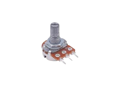
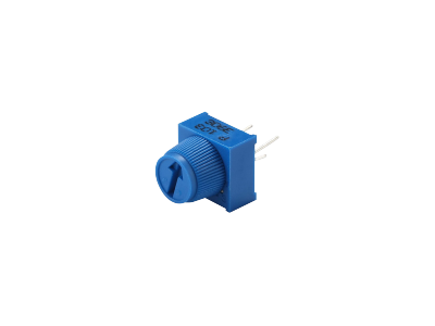
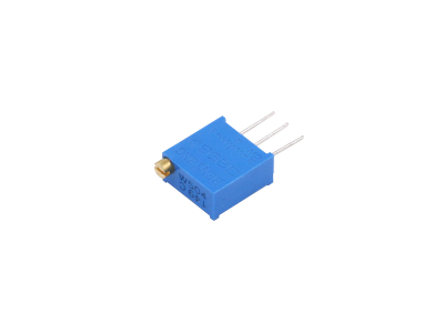
Two resistors or a potentiometer can be used for the resistor voltage divider. Options for purchasing resistor kits and potentiometers are given below.
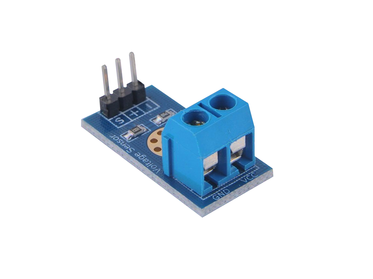
The Voltage Sensor module given below has a built-in resistor voltage divider circuit with 30kΩ and 7.5kΩ resistors that can reduce the voltage by 5x.
BSS138 N-channel MOSFET
The BSS138 N-channel MOSFETMetal-Oxide-Semiconductor Field-Effect Transistor (BSS138 Datasheet PDF) allows bidirectional voltage conversion on the same line as shown in the figure below.
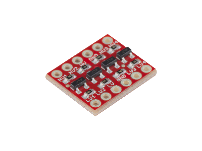
The BSS138 are surface mount components, but also come prepackaged into modules known as Logic Level Converters or Shifters. These modules have two different sides: one side for Low Voltage (LV) at 3.3V and the other side for High Voltage (HV) at 5.0V. An example of Logic Level Converter from SparkFun and Adafruit are shown in the figures below.
The main advantage the BSS138 FET Logic Level Converter modules have over the resistor voltage divider is the channels are bidirectional rather than unidirectional. However, on both types of circuits the maximum data transfer rate is reduced by higher resistor values in the circuit because it increases the rise time of the signal. The Logic Level Converter modules should work for speeds up to about 1MHz, sufficient for UARTUniversal Asynchronous Receiver-Transmitter and I2CInter-Integrated Circuit. Also referred to as IIC or I2C. communication. For faster communication protocols above 1MHz, such as SPISerial Peripheral Interface, a proper buffer/driver level shifter IC is recommended.
Logic Level Shifter ICs
74AHCT125
The 74AHCT125 Quad Buffer ICIntegrated Circuit can be used to shift in one direction only, such as converting 3V logic up to 5V, with push-pull outputs lines, such as SPISerial Peripheral Interface, mono directional lines, parallel bus, and other logic interfaces. It does not work with bi-directional open-drain output pull-up based devices such as I2CInter-Integrated Circuit. Also referred to as IIC or I2C. or 1-Wire1-Wire is a half-duplex serial protocol using a single data line plus ground reference for communication..
The 74AHCT125 has a voltage supply VCCVoltage Collector Collector (VCC) is the supply voltage at the collector of a transistor. The double subscript notation of repeating letters "CC" is used to denote a power supply voltage that is relative to ground. from 4.5V to 5.5V DC. There are four independent inputs (A pins), each with their own output enable (OE) control pins, and four corresponding outputs (Y pins). If an input exceeds 2V and its OE pin is ground, the output will be a high level VCC. The maximum current output is 25mA. More details can be found in the 74AHCT125 Datasheet (PDF).
74LVC245
The 74LVC248 Octal Bus Transceiver ICIntegrated Circuit can interface 3.3V and 5V devices with push-pull outputs lines, such as SPISerial Peripheral Interface, mono directional lines, parallel bus, and other logic interfaces. It does not work with bi-directional open-drain output pull-up based devices such as I2CInter-Integrated Circuit. Also referred to as IIC or I2C. or 1-Wire1-Wire is a half-duplex serial protocol using a single data line plus ground reference for communication..
This chip has a voltage supply VCCVoltage Collector Collector (VCC) is the supply voltage at the collector of a transistor. The double subscript notation of repeating letters "CC" is used to denote a power supply voltage that is relative to ground. from 1.65V to 3.6V DC. There are eight independent inputs (A pins), all controlled with one output enable (OE) pin, and eight corresponding outputs (B pins). If an input exceeds 2V and the OE pin is ground, the output will be a high level VCC. The maximum current output is 50mA. More details can be found in the 74LVC248 Datasheet (PDF).
TXB
The TXB series are bi-direction logic level converters that are designed to work on push-pull outputs lines, such as SPISerial Peripheral Interface, mono directional lines, and parallel bus. They do not work with bi-directional open-drain output pull-up based devices, such as I2CInter-Integrated Circuit. Also referred to as IIC or I2C. or 1-Wire1-Wire is a half-duplex serial protocol using a single data line plus ground reference for communication., where the lines are bi-directional and their direction changes from one way to the other (input <-> output). More information on how to use TXB series translators can be found in the Texas Instruments Application Note Guide to Voltage Translation for TXB-Type Translators (PDF).
TXB0104
The TXB0104 IC (TXB0104 Datasheet PDF) is a 4-bit bi-directional voltage level translator with automatic direction sensing. Both SparkFun and Adafruit make breakout boards for the TXB0104 IC.
The TXB0104 has two separate configurable power-supply rails. The A port is designed to track VCCA that has a supply voltage from 1.2V to 3.6V DC. The B port is designed to track VCCB that has a supply voltage from 1.65V to 5.5V DC. This allows for universal low-voltage bidirectional translation between any of the 1.2V, 1.5V, 1.8V, 2.5V, 3.3V, and 5V voltage nodes. VCCA should not exceed VCCB to avoid possible damage to the chip.
The outputs are all enabled with one output enable (OE) pin. When the OE pin is low, all outputs are placed in the high-impedance state. To ensure the high-impedance state during power up or power down, OE should be tied to GND through a pull-down resistor, where the minimum value of the resistor is determined by the current-sourcing capability of the driver.
The bandwidth on the individual signal channels can range from 20MbpsMegabits per second up to 100Mbps, depending on the high and low side voltages, making the TXB0104 suitable for higher speed signals such as SPISerial Peripheral Interface.
TXB0108
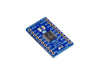
The TXB0108 IC (TXB0108 Datasheet PDF) is a 8-bit bi-directional voltage level translator with automatic direction sensing. The main difference between the TXB0104 and TXB0108 is the number of lines it can perform voltage level conversion on (the TXB0104 has four lines, whereas the TXB0108 has eight lines), otherwise they have the same functionality and specs. Adafruit makes a breakout board for the TXB0104 IC as shown in the figure below.
TXS
The TXS series are bi-direction logic level converters that are designed to work with either open-drain output pull-up based devices (I2CInter-Integrated Circuit. Also referred to as IIC or I2C., 1-Wire1-Wire is a half-duplex serial protocol using a single data line plus ground reference for communication.), or push-pull outputs lines (SPISerial Peripheral Interface, mono directional lines, and parallel bus).
TXS0108E
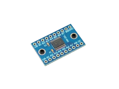
The TXS0108E IC (TXS0108E Datasheet PDF) is a 8-bit bi-directional voltage level translator with automatic direction sensing. SparkFun has a breakout board for the TXS0108E IC and there are also generic breakout boards available.
The TXS0108E has two separate configurable power-supply rails. The A port is designed to track VCCA that has a supply voltage from 1.4V to 3.6V DC. The B port is designed to track VCCB that has a supply voltage from 1.65V to 5.5V DC. This allows for universal low-voltage bidirectional translation between any of the 1.2V, 1.5V, 1.8V, 2.5V, 3.3V, and 5V voltage nodes. VCCA should not exceed VCCB to avoid possible damage to the chip.
The outputs are all enabled with one output enable (OE) pin. When the OE pin is low, all outputs are placed in the high-impedance state. To ensure the high-impedance state during power up or power down, OE should be tied to GND through a pull-down resistor, where the minimum value of the resistor is determined by the current-sourcing capability of the driver.
The TXS0108E can transmit data between ports at max speeds of 110Mbps (push/pull) or 1.2Mbps (open drain) so you can use a 3.3V SPI device with a 5V microcontroller.
Conclusion
This overview covered common logic level converters, such as Resistor Voltage Dividers, BSS138 FET, Logic Level Shifter ICs, TXB modules, and TXS modules. Each have trade-offs on data transfer direction, speed, output configuration (push-pull, open-drain), and cost.
The simplest and least expensive approach to converting voltage is using a resistive voltage divider, but it only provides a one-way voltage drop (unidirectional) that can only be used for low speed data transfers. The maximum data transfer speed achievable with a resistor divider depends on the resistor values, capacitive loading, and the length and quality of the cabling.
The BSS138 FET Logic Level Converter modules are bidirectional that can handle speeds up to about 1MHz, sufficient for UART and I2C communication. For faster communication protocols above 1MHz, such as SPI, a proper buffer/driver level shifter IC is recommended.
The 74AHCT125, 74LVC248, and TXB series ICs shift in one direction only, such as converting 3V logic up to 5V, with push-pull outputs lines, such as SPI, mono directional lines, parallel bus, and other logic interfaces. However, they both do not work with bidirectional open-drain output pull-up based devices such as I2C or 1-Wire.
The TXS series are bidirection logic level converters with automatic direction sensing that are designed to work at high speeds with either open-drain output pull-up based devices (I2C, 1-Wire), or push-pull outputs lines (SPI, mono directional lines, and parallel bus). The TXS0108E can transmit data between ports at max speeds of 110Mbps (push/pull) or 1.2Mbps (open drain).





(0) Comments
Sign in to leave a comment
Sign In