Interfacing Digital Inputs
Updated: 24Jun2024 08:11:19 UTC 2024-06-24T08:11:19Z
Rating: (0 reviewsThis article has not been rated yet)
If you plan on using a microcontroller (MCUMicrocontroller Unit) or Single Board Computer (SBCSingle Board Computer) to read a digital signal from a device with a separate power supply, you need to ensure that both the voltage and current levels between the devices are compatible. For example, many MCUs and SBCs have their GPIOGeneral Purpose Input Output rated at 3.3V, so interfacing them with an external 5V device requires external circuitry that drops the voltage from 5V to 3.3V.
This article discusses the benefits and limitations of different techniques used to protect devices from over-voltage and over-current.
Resistor Voltage Divider
A typical scenario where voltage conversion is needed is when using a 5V sensor with a 3.3V MCU or SBC to read the sensor. The simplest way to step the voltage down is to use a resistor voltage divider shown in the figure below.
Resistor values are chosen so their relative ratios divide the voltage from 5V to 3.3V. The resistor values are also chosen determine the amount of current being used and the resistor power ratings. Lower values of resisters in the divider will draw more current, whereas higher resistors lower the current.
There are some limitations with the resistor voltage divider when interfacing digital circuits.
- They are unidirectional by only stepping down the voltage from device to another. Two-way communication, such as with UARTUniversal Asynchronous Receiver-Transmitter/I2CInter-Integrated Circuit. Also referred to as IIC or I2C./SPISerial Peripheral Interface, requires bidirectional level shifting.
- The data transfer rate is reduced by higher resistor values in the circuit because it increases the rise time of the signal.
- There is no over-voltage protection beyond whatever margin is accounted for in the resistor values chosen.
Two resistors or a potentiometer can be used for the resistor voltage divider. Options for purchasing resistor kits and potentiometers are given below.


Zener Diode Over-Voltage Protection
If there is a possibility that the voltage on the external device may exceed 5V, an overprotection 3.3V Zener diode can be used between the GPIO pin and GNDCommon Ground to limit (clamp) the voltage at 3.3V for the GPIO. If the voltage starts to exceed 3.3V at the GPIO, this will cause the Zener diode to "break down" and allow current to flow through diode to GND, ensuring the voltage that reaches the GPIO is no more than 3.3V.
Electrical Isolation
Opto-Isolation
An optocoupler (or opto-isolator) can be used to electrically isolate the MCU or SBC from an external device to avoid sinking large current into the GPIO. An optocoupler consists of an LEDLight Emitting Diode emitter next to a photodetector transistor that are separated by an insulating film. When current flows through the LED emitter, it transmits light to the photodetector transistor that allows a separate current through the photodetector transistor. When the LED emitter is off, no light falls on photodetector transistor and almost no current flows through it. The figure below shows an optocoupler interface between an MCU or SBC and an external device operating at a higher voltage.
Optocouplers are useful for isolating circuits, but have a few disadvantages.
- Higher power consumption needed for the supplying current for the emitting diode inside the optocoupler
- Reliability issues due to failure of the emitting diode, as well as interface contamination and thermo-mechanical stress associated with moisture absorption
- Propagation delays in the optocoupler make data rates slower compared to alternative devices such as magnetic isolators. For example, the PC817 optocoupler has about a 5kHz data rate and high speed optocouplers like the 6N137 get up to 10MHz, whereas the ADUM1201 magnetic isolator gets up to 125MHz.
Different options for purchasing optocouplers as ICIntegrated Circuits or modules are given below.


Magnetic Isolation
Digital magnetic isolators use magnetic coupling, where data is transferred by a changing magnetic field that induces current in a separate coil. Magnetic isolators surpass optocouplers in terms of size, operational frequency, and power consumption. The figure below shows an magnetic isolator interface between an MCU or SBC and an external device operating at a higher voltage.
One of the disadvantages of magnetic isolators is they are more prone to magnetic interference than optocouplers since they use transient magnetic fields to transfer data. This is something to be concerned about if your device is going to be used near a large motor.
Different options for purchasing magnetic isolators are given below.


Logic Level Converter
The voltage shifting circuits given so far only provide a voltage conversion in one direction. However, data communication lines need to be bidirectional and some data buses, like I2CInter-Integrated Circuit. Also referred to as IIC or I2C., need that level translated in both directions on a single line. The BSS138 N-channel MOSFETMetal-Oxide-Semiconductor Field-Effect Transistor (Datasheet PDF) allows bidirectional voltage conversion on the same line as shown in the figure below.
The BSS138 are surface mount components, but also come prepackaged into modules known as Logic Level Converters or Shifters. These modules have two different sides: one side for low voltage (LV) at 3.3V and the other side for high voltage (HV) at 5.0V. An example of Logic Level Converter from SparkFun and Adafruit are shown in the figures below.
The main advantage the BSS138 N-channel MOSFET Logic Level Converter modules have over the resistor voltage divider is the channels are bidirectional rather than unidirectional. However, on both types of circuits the maximum data transfer rate is reduced by higher resistor values in the circuit because it increases the rise time of the signal. The Logic Level Converter modules should work for speeds up to about 1MHz, sufficient for UARTUniversal Asynchronous Receiver-Transmitter and I2CInter-Integrated Circuit. Also referred to as IIC or I2C. communication.
For faster communication protocols above 1MHz, such as SPISerial Peripheral Interface, a proper buffer/driver level shifter ICIntegrated Circuit is recommended (4-wire SPI has no bidirectional pins, but 3-wire does). One such IC is the TXS0108E by Texas Instruments with a maximum data rate of 110Mbps. This IC is available in a module as shown in the figure below.
A list of different options for purchasing Logic Level Converters is provided below.


Conclusion
This concludes interfacing externally powered circuits to extract a digital signal. The simplest approach to reducing voltage is using a resistive voltage divider, but this only provides a one-way voltage drop, it may reduce high speed data transfers, and does not have any overvoltage protection. The addition of a zener diode or using an isolator IC can provide overvoltage protection, while logic level converters in the form of a module is the most convenient to use for high speed data transfer.
Related Content
Created:
19Apr2023 17:32:36 UTC
2023-04-19T17:32:36Z
Updated:
19Aug2024 19:24:35 UTC
2024-08-19T19:24:35Z
Rating: (0 reviewsThis article has not been rated yet)
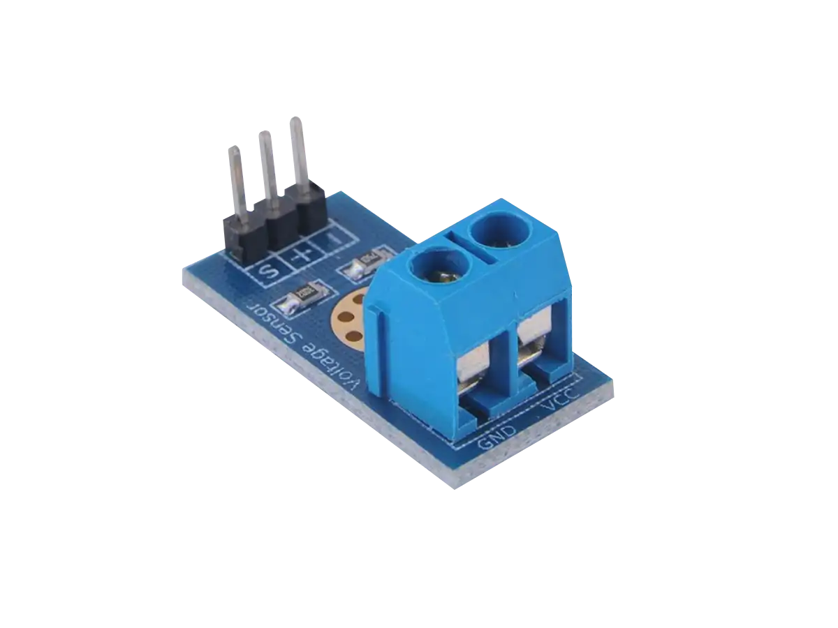
The resistor voltage divider sensor module is a device used to measure voltages beyond the range of your ADC, making the input voltage 5x smaller.

Created:
10Jan2024 07:43:00 UTC
2024-01-10T07:43:00Z
Updated:
26Aug2024 04:58:53 UTC
2024-08-26T04:58:53Z
Rating: (0 reviewsThis article has not been rated yet)
Overview of the different kinds of logic level converters.
- Resistor Voltage Divider
- BSS138 FET IC and Modules
- 74AHCT125 and 74LVC248 ICs
- TXB0104, TXB0108, and TXS0108E Modules
(0) Comments
Sign in to leave a comment
Sign In