Voltage Sensor Module (Resistor Divider)
Updated: 19Aug2024 19:24:35 UTC 2024-08-19T19:24:35Z
Rating: (0 reviewsThis article has not been rated yet)
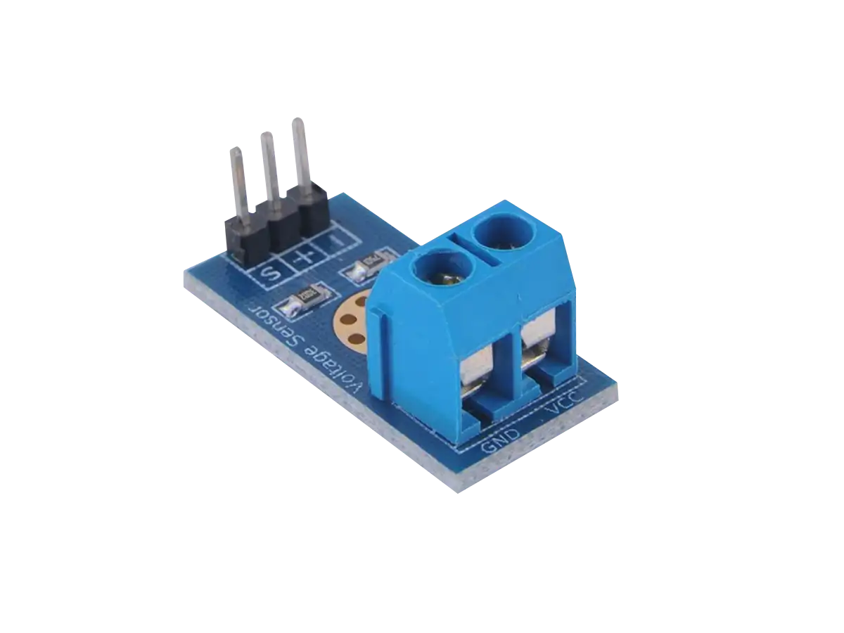
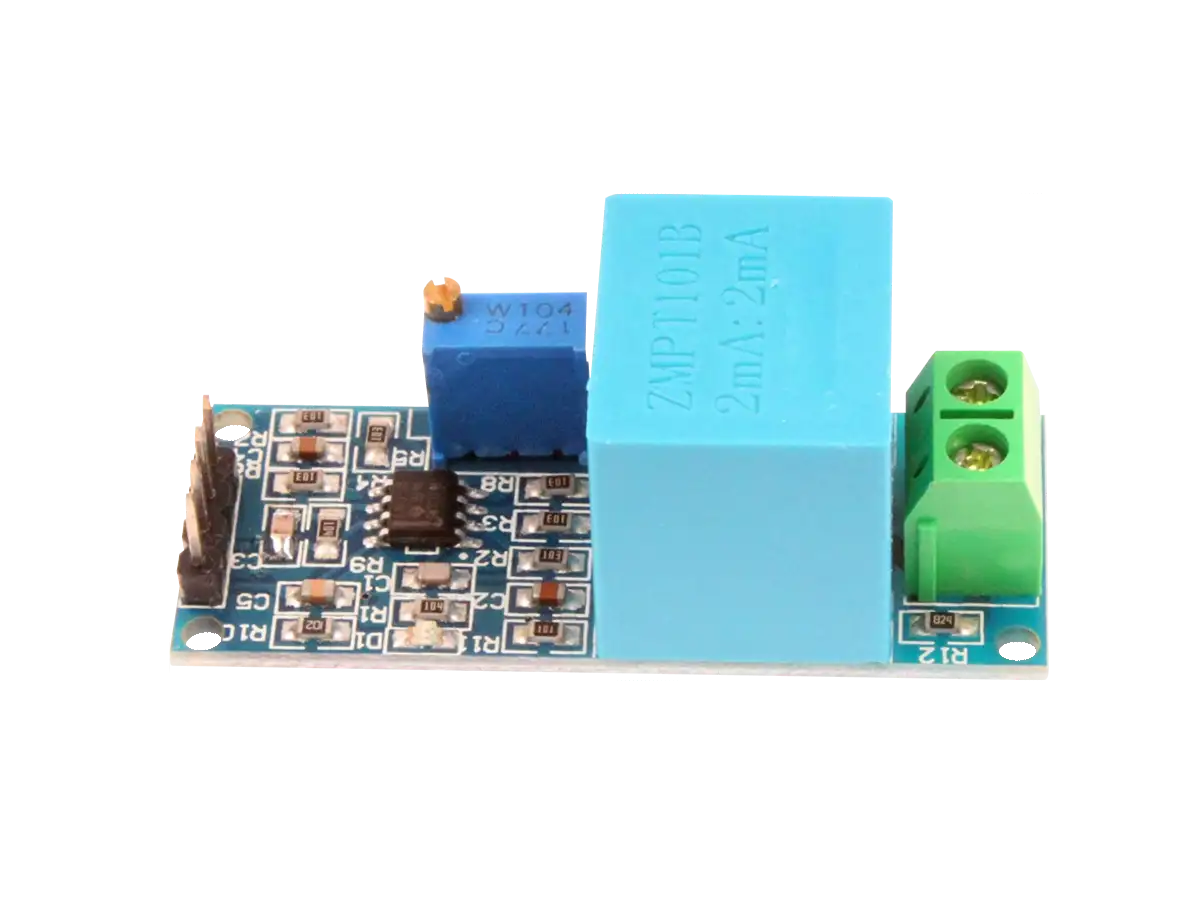
The voltage sensor module shown in the title figure is a convenient device to measure voltages beyond the range of your ADCAnalog-to-Digital Converter (ADC, A/D, or A-to-D). It is small (typically 4cm x 3cm x 2cm), portable, and easy to hook up. This sensor incorporates a resistor voltage divider that makes the input voltage 5x smaller.
The input voltage range of this module depends on the maximum voltage of the device used to read from this module. For example, when used with an ADC with a 5V range, such as an Arduino Uno R3, this sensor has an input voltage range from 0V up to 25V. When used with an ADC with a 3.3V range, such as a RPiRaspberry Pi Pico or ESP32, this sensor has an input voltage range from 0V up to about 16V.
The voltage sensor module board layout, how to hook it up to a device, and its limitations will be discussed.
Board Layout
The board layout of this sensor module, including inputs and outputs, are provided in the illustration below along with a table defining the pin functions.
| Pin | Function |
|---|---|
| VCC | Input positive terminal of the external voltage source being measured |
| GND | Negative terminal of the external voltage source (ground) |
| S | Analog output pin voltage to connect to your ADC |
| + | Not connected |
| - | Ground connection pin to the device that reads in the analog voltage |
A schematic of this sensor module is given below. It consists of two precision (1% tolerance) resistors in series from the input VCC. The output reads the voltage across the lower resistor (7.5kΩ).
Hookup
The hookup of the voltage sensor module to a microcontroller board or other device with an ADC is simple. The "S" signal pin is connected to the analog input (ADC) of the device and the "-" pin is connected to ground of the device. Nothing needs to be connected to the "+" pin and you can leave it floating.
On the other end of the module, the VCC and GND screw terminals are connected to the positive and negative of the voltage source being measured, such as a battery shown in the illustration below.
Limitations
There are a few limitations with resistor voltage dividers.
- Output has high impedance that can be a problem for an ADC
- Only attenuates signals and cannot amplify a signal. Small signals relative to your ADC range need to be amplified to maximize the resolution.
- No over-voltage protection.
- Inefficient with power from dissipation by Joule's heating.
For high-power applications, reactive voltage dividers using capacitors and/or inductors are preferred because they do not dissipate as much power as resistors. For battery applications, a fuel gauge IC would be better suited because of its low power operation and it can give you the battery percentage that handles voltage nonlinearity and unstable conditions (e.g., changes in the battery due to temperature, loading, aging, and self-discharge).
Related Content


Products

Created:
12Apr2023 21:11:53 UTC
2023-04-12T21:11:53Z
Updated:
07May2024 09:46:17 UTC
2024-05-07T09:46:17Z
- Two precision resistors (1% tolerance)
- 0V to 25V DC input range
- 0V to 5V output with 4.89mV resolution
(0) Comments
Sign in to leave a comment
Sign In