Voltage Sensors
Updated: 19Aug2024 07:19:00 UTC 2024-08-19T07:19:00Z
Rating: (0 reviewsThis article has not been rated yet)
A voltage sensor is used measure, detect, or monitor the electrical voltage on a device, battery, or power line. They can measure or detect ACAlternating Current or DCDirect Current voltage levels by stepping down the input voltage to a level suitable for a device that processes the signal, such ADCAnalog-to-Digital Converter (ADC, A/D, or A-to-D)s, microcontroller boards, or SBCSingle Board Computers.
The output of voltage sensors come in the form of an analog voltage (proportional to the input voltage) or digital (on/off or a communication protocal such as I2CInter-Integrated Circuit. Also referred to as IIC or I2C.). What will be covered here are voltage sensors that come in the form of modules to make it easier to interface to, such as Resistor Voltage Divider Sensors, Li-ionLithium-ion/LiPoLithium Polymer Battery Fuel Gauge Modules, and AC Mains Voltage Sensors.
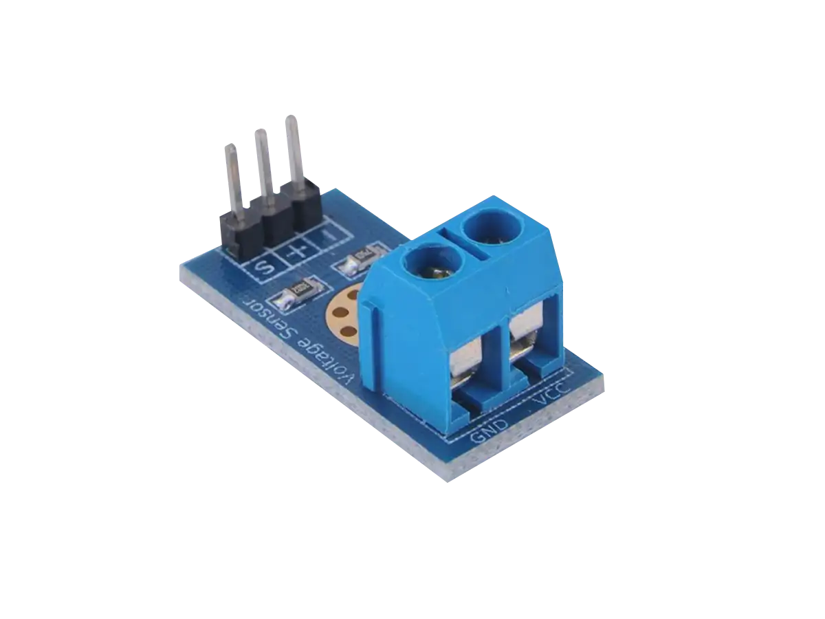
Resistor Voltage Divider Sensor Module
The Resistor Voltage Divider Sensor Module shown below is a convenient device to measure voltages beyond the range of your ADC. It is small (typically 4cm x 3cm x 2cm), portable, and easy to hook up.
This sensor incorporates a resistor voltage divider that makes the input voltage 5x smaller. When used with an ADC with a 5V range, such as an Arduino, this sensor has an input voltage range of up to 25V. When used with an ADC with a 3.3V range, such as a RPi Pico, this sensor has an input voltage range of about 16V.
The inputs and outputs of this sensor module are provided in the illustration and table below. A schematic of the module is also given below.
| Pin | Function |
|---|---|
| VCC | Input positive terminal of the external voltage source being measured |
| GND | Negative terminal of the external voltage source (ground) |
| S | Analog output pin voltage to connect to your ADC |
| + | Not connected |
| - | Ground connection pin to the device that reads in the analog voltage |
There are a few limitations with resistor voltage dividers.
- Output has high impedance that can be a problem for an ADC
- Only attenuates signals and cannot amplify a signal. Small signals relative to your ADC range need to be amplified to maximize the resolution.
- No over-voltage protection.
- Inefficient with power from dissipation by Joule's heating.
For high-power applications, reactive voltage dividers using capacitors and/or inductors are preferred because they do not dissipate as much power as resistors.
For battery applications, a fuel gauge IC would be better suited because of its low power operation and it can give you the battery percentage that handles voltage nonlinearity and unstable conditions (e.g., changes in the battery due to temperature, loading, aging, and self-discharge).
Battery Fuel Gauges
Single Li-ionLithium-ion and LiPoLithium Polymer battery cells have a nominal voltage of 3.7V. However, when the battery is fully charged you may see about 4.2V (max) which quickly lowers to 3.7 (nominal) when used and eventually drop down to about 3.0V (min) when depleted. Li-ion and LiPo batteries can be damaged by being discharged too far so there is usually protection circuitry built on top of the cell that will shut off the battery if the voltage drops below a certain threshold (usually 3.0V).
Simply measuring the battery voltage to monitor its charge percentage would give inaccurate results because the relationship is nonlinear as shown in the figure below. This curve depends on many factors, such as number of charge/discharge cycles, age, temperature, and the load it is connected. Accounting for this nonlinear behavior to give a valid charge percentage is what battery fuel gauges were designed for.
Some common terms you will see relating to battery fuel gauges are given below.
- Open Circuit Voltage (OCV):
- The voltage on a battery when no external load is connected.
- State Of Charge (SoC):
- The level of charge of an electric battery relative to its capacity. SoC is usually expressed as percentage (0% = empty, 100% = full), calculated as SoC = RM/FCC, where RM is the remaining capacity and FCC is the Full Charge Capacity. Since SoC depends on different charging/discharging currents, temperatures and aging effects, and the load you will pull from it, the term is defined more clearly with ASOC (Absolute State-Of-Charge) and RSOC (Relative State-Of-Charge).
- Full Charge Capacity (FCC):
- FCC refers to the amount of charge a battery can hold and the total amount of energy you could extract from the fully charged state until empty.
- Remaining Capacity (RM):
- RM represents how much energy you will likely be able to extract from the battery from the current point in time until the system can no longer operate. RM will continue to decrease as the pack ages.
- Absolute State Of Charge (ASOC):
- ASOC is a reference calculated by Design Capacity which is a fixed capacity from when the battery is manufactured, expressed as ASOC = RM / Design Capacity. A fully charged new battery will have 100% ASOC, but a fully charged aging battery could be less than 100% because of different charge/discharge conditions. ASOC will eventually not be able to reach 100%, because the Design Capacity never changes, whereas RM will continue to decrease as the pack ages.
- Relative State Of Charge (RSOC):
- The RSOC is the ratio of the current absolute state of charge to the maximum capacity of an electric battery, expressed as RSOC = RM / FCC. A fully charged battery's RSOC is always 100% and a fully discharged battery has 0% RSOC.
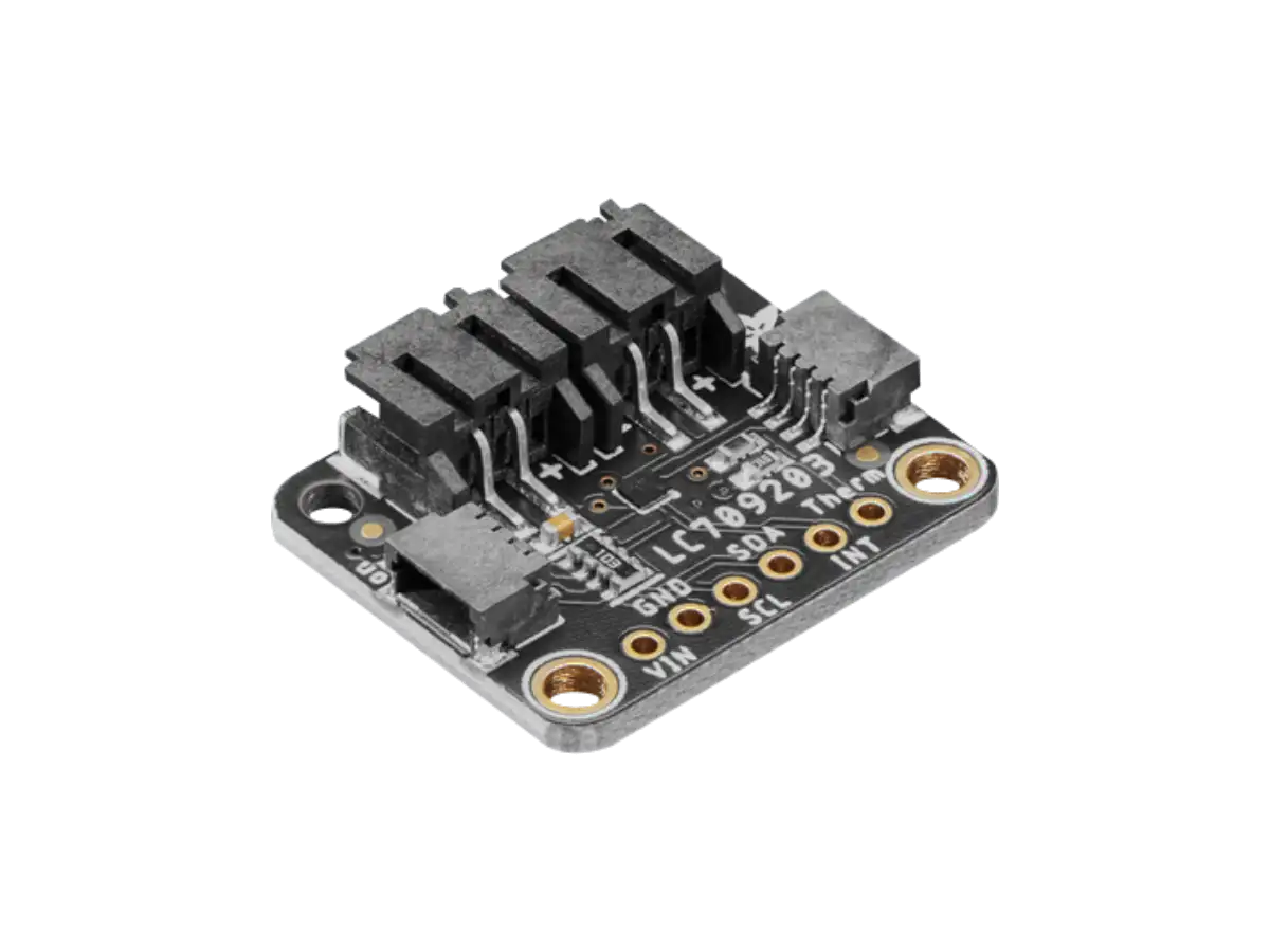
LC709203F
The Adafruit LC709203F module (PID 4712) shown in the figure below is a Battery Fuel Gauge and Monitor based on the LC709203F IC by On Semiconductor (onsemi) that measures the voltage and charge percentage (0% empty to 100% full charge) on a single cell Li-ion or LiPo battery and decodes the non-linear voltage behavior of the battery to get a valid percentage.
The LC709203F IC has a non-linear voltage algorithm called HG-CVR, which provides an accurate RSOCRelative State Of Charge even under unstable conditions (e.g., changes in the battery due to temperature, loading, aging, and self-discharge). This module outputs the battery's voltage and percentage data over I2CInter-Integrated Circuit. Also referred to as IIC or I2C. and operates with 3.3V or 5.0V for both power and communication, so it should work with any microcontroller or SBCSingle Board Computer with an I2C interface.
Adafruit has software libraries available for Arduino and CircuitPython/Python to read the battery voltage and percentage, where you can set the battery pack size to help tune the percentage calculation.
To learn more about the LC709203F IC and the Adafruit breakout specs, pin definitions, board layout, schematic, and hookup, check out the LC709203F Battery Fuel Gauge article below.
Created:
19Apr2023 23:32:02 UTC
2023-04-19T23:32:02Z
Updated:
19Aug2024 23:25:02 UTC
2024-08-19T23:25:02Z
Rating: (0 reviewsThis article has not been rated yet)
The LC709203F IC by On Semiconductor measures the voltage on a single cell Li-ion or LiPo battery and decodes the non-linear voltage behavior of the battery to get a valid percentage. Adafruit has a breakout board for this IC with external circuitry, an onboard power LED, and connectors.
MAX17043
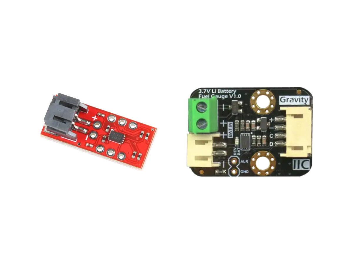
The SparkFun MAX17043 module (TOL-20680) shown in the figure below is a Battery Fuel Gauge based on the MAX17043 IC by Maxim Integrated (a subsidiary of Analog Devices) that measures the voltage on a single cell Li-ion or LiPo battery and decodes the non-linear voltage behavior of the battery to get a valid percentage.
The MAX17043 IC has a non-linear voltage algorithm called ModelGauge™ that provides an accurate RSOCRelative State Of Charge even under unstable conditions (e.g., changes in the battery due to temperature, loading, aging, and self-discharge).
This module outputs the battery's voltage and percentage data over I2C and operates with 3.3V or 5.0V for both power and communication, so it should work with any microcontroller or SBCSingle Board Computer with an I2C interface. SparkFun has software libraries available for to read the battery voltage and percentage (GitHub SparkFun MAX17043 Arduino Library).
Another module based on the MAX17043 is the Gravity I2C 3.7V Li Battery Fuel Gauge made by DFRobot. This board shown below has a 2-Pin JST 2.0PH connector or screw terminal to hook up the battery to and a 4-Pin JST 2.0PH for the power (VCC, GND) and I2C data lines (SCL, SDA).
To learn more about the MAX17043 IC and these breakout boards, including their specs, pin definitions, board layout, schematic, and hookup, check out the MAX17043 Battery Fuel Gauge article below.
Created:
21Apr2023 18:21:42 UTC
2023-04-21T18:21:42Z
Updated:
20Aug2024 06:21:37 UTC
2024-08-20T06:21:37Z
Rating: (0 reviewsThis article has not been rated yet)
The MAX17043 IC by Maxim Integrated measures the voltage on a single cell LiPo/Li-ion battery and accounts for the non-linear voltage behavior of the battery to get a charge percentage. Both SparkFun and DFRobot have breakout boards for this IC with external circuitry and a 2-Pin JST battery connector.
MAX17048
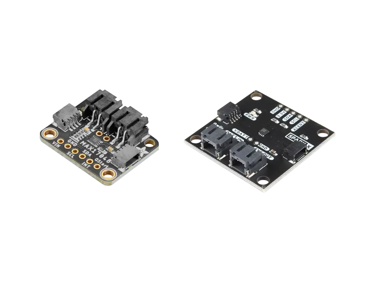
The Adafruit MAX17048 module (PID 5580) shown in the figure below is a Battery Fuel Gauge and Monitor based on the MAX17048 IC by Maxim Integrated (a subsidiary of Analog Devices) that measures the voltage on a single cell Li-ionLithium-ion or LiPoLithium Polymer battery and decodes the non-linear voltage behavior of the battery to get a valid percentage.
The MAX17048 IC has a non-linear voltage algorithm called ModelGauge™ that provides an accurate Relative State of Charge (RSOC) even under unstable conditions (e.g., changes in the battery due to temperature, loading, aging, and self-discharge). This module outputs the battery's voltage and percentage data over I2C and operates with 3.3V or 5.0V for both power and communication, so it should work with any microcontroller or SBC with an I2C interface.
Adafruit has software libraries available for Arduino and CircuitPython/Python to read the battery voltage and percentage, as well as setting alerts and low power mode.
The SparkFun MAX17048 Fuel Gauge Sensor Module (SPX-17715) shown in the figure below is very similar to the Adafruit board with the same connectors and I/O. The SparkFun board also has libraries for Arduino to read the battery voltage and percentage (GitHub SparkFun Max17048 Arduino Library).
To learn more about the MAX17048 IC and these breakout boards, including their specs, pin definitions, board layout, schematic, and hookup, check out the MAX17048 Battery Fuel Gauge article below.
Created:
22Apr2023 01:23:15 UTC
2023-04-22T01:23:15Z
Updated:
20Aug2024 22:59:18 UTC
2024-08-20T22:59:18Z
Rating: (0 reviewsThis article has not been rated yet)
The MAX17048 IC by Maxim Integrated measures the voltage on a single cell LiPo/Li-ion battery and accounts for the non-linear voltage behavior of the battery to get a charge percentage. Both Adafruit and SparkFun have breakout boards for this IC with external circuitry and a 2-Pin JST battery connector.
AC Mains Voltage Sensors
AC 220V Voltage Detector Module
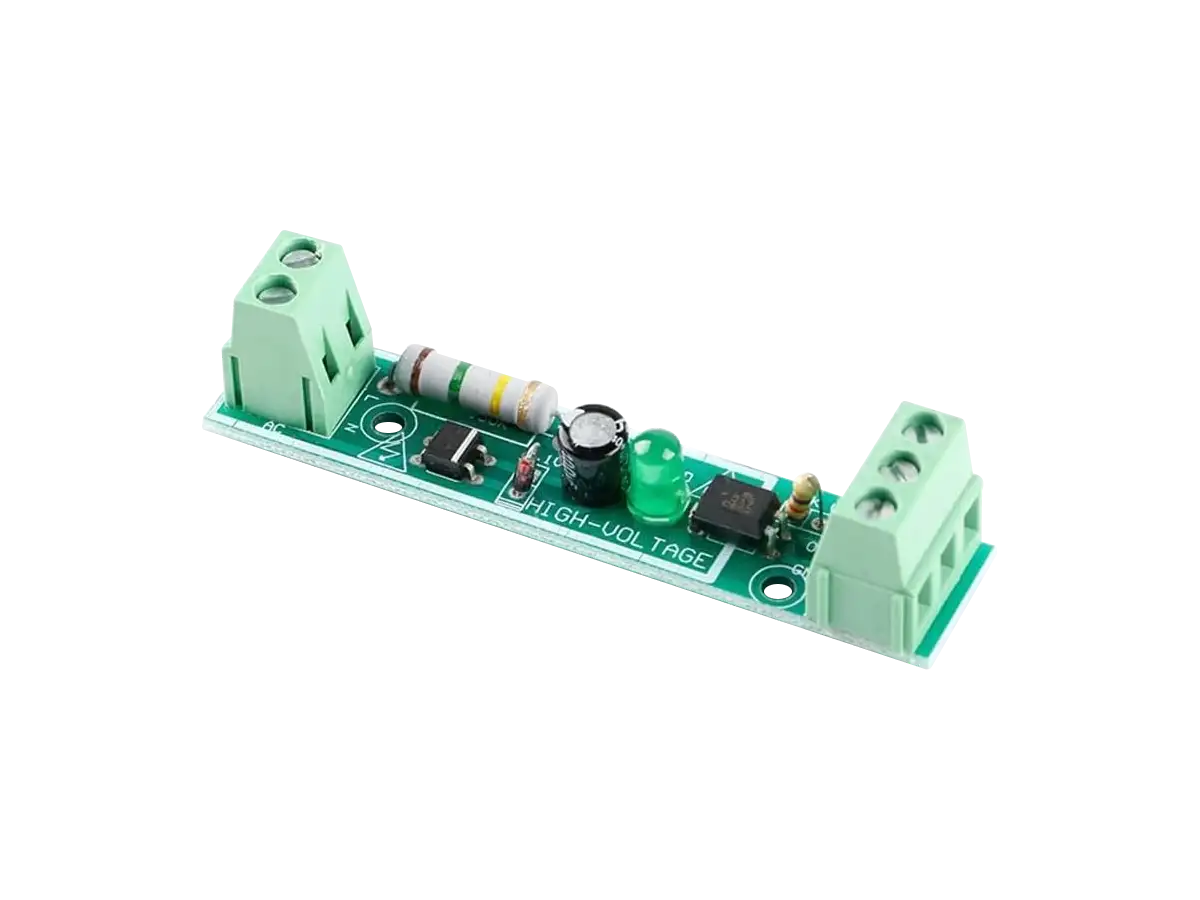
The AC 220V mains voltage detector shown in the figure below can be used to detect when the power on a line from an outlet is turned on/off, such as lights, appliances, or determining when power outages occur.
The inputs and outputs for this module are shown in the figure below. There are two screw terminal inputs: the AC power line (L) and the AC neutral line (N). The large resistor on the board limits the current from the large input voltage applied and the rest of the circuit filters and detects the signal.
The chip on the right side of the board is an optocoupler, powered by the VCC and GND terminals, which isolates the high input voltage from the output terminal. The board has a green power indicator LED that turns on when AC power is applied to the inputs L and N (it is not connected to VCC and GND).
This board has only a 1 channel input, but there are also 3 channel and 8 channel boards available (shown below).
To learn more about how the AC Mains Voltage Detector Module works and other alternatives, check out the AC Mains Voltage Detectors article below.
Created:
22Apr2023 20:45:24 UTC
2023-04-22T20:45:24Z
Updated:
21Aug2024 00:17:28 UTC
2024-08-21T00:17:28Z
Rating: (0 reviewsThis article has not been rated yet)
The Mains AC 220V voltage detector can be used to detect when the power on a line from an outlet is turned on/off, such as lights, appliances, or determining when power outages occur.
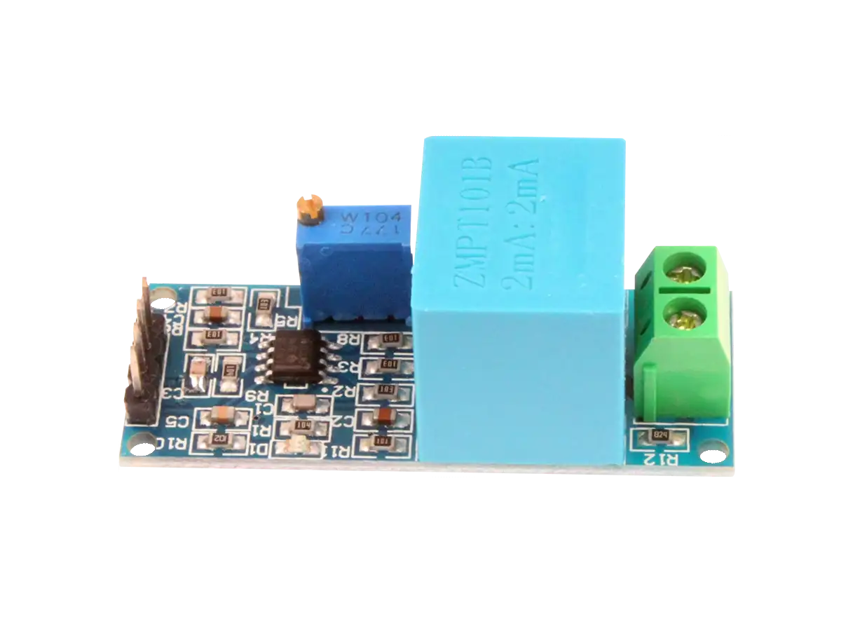
ZMPT101B AC Voltage Sensor Module
The ZMPT101B Single Phase AC Voltage Transformer Module can measure AC voltages up to ±250V (50Hz/60Hz) and outputs an AC voltage between 0V and VCC with an DC offset of VCC/2, where VCC can be 5V to 30V DC. This module comes with a multi turn trim potentiometer for adjusting the amplitude of the output waveform around the DC offset to make the output range suitable for an external ADC.
To learn more about the ZMPT101B Module, including specs, pin definitions, board layout, schematic, hookup, and calibration, check out the ZMPT101B AC Voltage Transformer Sensor Module article below.
Created:
23Apr2023 20:06:03 UTC
2023-04-23T20:06:03Z
Updated:
21Aug2024 03:42:09 UTC
2024-08-21T03:42:09Z
Rating: (0 reviewsThis article has not been rated yet)
The ZMPT101B AC Voltage Transformer Sensor Module can measure AC voltages up to ±250V (50Hz/60Hz) and outputs an analog voltage in a range suitable for a microcontroller ADC. This module can be used to measure 120V/220V AC mains household outlet voltage and waveform.
Conclusion
The voltage sensors covered here are used measure, detect, or monitor the electrical voltage on a device, battery, or power line. They measure voltage by stepping down the input voltage to a level suitable for a device that processes the signal, such ADCs, microcontroller boards, or SBCs.
- DC voltage can be stepped down from 25V to 5V or 16V to 3.3V with the Resistor Voltage Divider Sensor Module.
- Li-ion and LiPo Battery Charge Percentage can be measured with LC709203F, MAX17043, or MAX17048 Fuel Gauge Modules.
- AC Mains Voltage can be detected with the AC 220V Voltage Detector.
- The AC waveform can measured with the ZMPT101B AC Voltage Transformer Module.
Each of these sensors come in the form of modules to make them easier to interface to.


(0) Comments
Sign in to leave a comment
Sign In