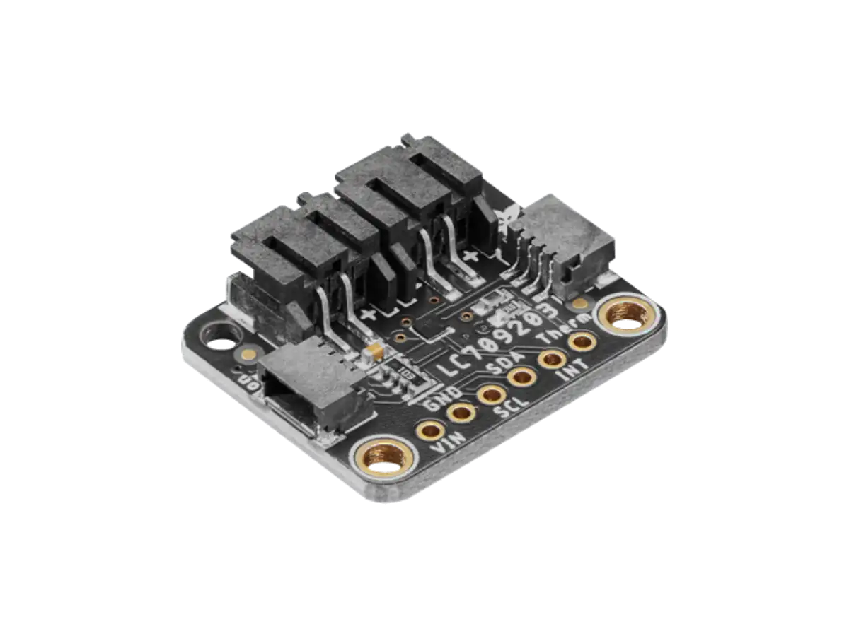
MAX17043 Battery Fuel Gauge
Updated: 20Aug2024 06:21:37 UTC 2024-08-20T06:21:37Z
Rating: (0 reviewsThis article has not been rated yet)
The MAX17043 ICIntegrated Circuit by Maxim Integrated (a subsidiary of Analog Devices) measures the voltage on a single cell LiPoLithium Polymer or Li-ionLithium-ion battery and accounts for the non-linear voltage behavior of the battery to get a charge percentage. This IC outputs the battery's voltage and percentage data over I2CInter-Integrated Circuit. Also referred to as IIC or I2C. and also has a separate alert output that tells you when the charge has dropped below a certain percentage.
This hardware overview of the MAX17043 Fuel Gauge covers the IC, SparkFun Module, and DFRobot Module, including specs, pinout, board layout, and operation.
The SparkFun and DFRobot breakout boards have external circuitry and a 2-pin JSTJapan Solderless Terminal battery connector to make it easier to interface to the MAX17043 IC. The SparkFun module has pin through holes for its connections, whereas the DFRobot also has a 4-Pin GravityGravity connectors are DFRobot's name for 3 or 4 pin JST PH connectors with 2.0mm pitch. These connectors were implemented on DFRobot's boards to make it easy to plug-n-play various sensors and devices without soldering and wiring. The DFRobot Gravity connectors are cross-compatible with Seed Studio Grove and Adafruit’s STEMMA connectors. connector and an extra 2-Pin screw terminal for the battery connection.
MAX17043 IC
Overview
The MAX17043 is a Battery Fuel Gauge IC that measures the Relative State Of Charge (RSOCRelative State Of Charge) on a single-cell 3.7V (5.0V max) Li-ion or LiPo battery. The MAX17043 outputs the battery's cell voltage and charge percentage between 0% (empty) and 100% (full charge) through an I2C interface.
The MAX17043 IC has a non-linear voltage algorithm called ModelGaugeTM that provides an accurate RSOC even under unstable conditions (e.g., changes in the battery due to temperature, loading, aging, and self-discharge). The ModelGauge algorithm eliminates the need for battery relearn cycles and an external current-sense resistor.
The MAX17043 outputs the battery's voltage and percentage data over I2C and also has a separate alert output (active-low) that tells you when the charge has dropped below a certain percentage. The threshold for the alert is configurable over I2C.
The MAX17043 also features a sleep mode by holding both I2C lines, SDASerial Data Line and SCLSerial Clock (SCL) is the output clock signal line from the master device. Also referred to as SCK, SCLK, or CLK., to a logic-low level. In sleep mode, all IC operations are halted and power drain of the IC is greatly reduced (1μA typical, 3μA max). A rising edge on SDA or SCL wakes up the IC.
Specs
| Feature | Description |
|---|---|
| IC Info | Maxim Integrated MAX17043 1S Fuel Gauge with Low-Battery Alert |
| Input | The battery input voltage can be up to 5.0V. Note that the nominal voltage of a single cell LiPo Battery is around 3.7V, but fully charged the voltage is at around 4.2V. |
| Output |
|
| Accuracy |
|
| Operating Voltage | VDD pin between 2.5V to 4.5V DC |
| Power Consumption |
|
| Package |
The IC is available in two packages:
|
| IC Size |
|
Pin Functions
The MAX17043 comes in two different packages: TDFNThin Dual Flat No-lead (TDFN) package 8-Pin and UCSPUltra Chip Scale Package 9-Bump. The pin configuration for the TDFN package is given in the diagram below followed by a table defining each of the pins.
| Pin | Name | Function |
|---|---|---|
| 1 | CTG | Connect To Ground during normal operation. |
| 2 | CELL | Battery voltage input connected to the battery's positive (+) pin. The voltage of the battery is measured through this pin. |
| 3 | VDD | Power-Supply Input with a range of 2.5V to 4.5V. Connect a 10nF typical decoupling capacitor close to pin. |
| 4 | GND | Ground. Connect to negative battery terminal. |
| 5 | ALRT | Alert Output. Open-Drain Active-Low interrupt signaling low state of charge. Connect to interrupt input of a microcontroller. |
| 6 | QSTRT | Quick-Start Input. Allows reset of the device through hardware. Connect to GND if not used. |
| 7 | SCL | I2C Serial Clock pin. This pin has an internal pull-down (0.2µA typical) to sense disconnection. |
| 8 | SDA | I2C Serial Data pin. Open-Drain. This pin has an internal pull-down (0.2µA typical) to sense disconnection. The host system provides the resistive pullup. |
Operation
The MAX17043 IC is powered with pin VDD using a voltage in the range of 2.5V to 4.5V. The battery voltage is measured with a 12-bit ADCAnalog-to-Digital Converter (ADC, A/D, or A-to-D) and then uses a non-linear battery model to effectively simulate the internal dynamics of the battery to determine the RSOC. The model considers the time effects of a battery caused by the chemical reactions and impedance in the battery.
When the battery level drops below a predefined threshold (defined by an I2C register), the ALRT pin output drops to a logic LOW level and sets the ALRT bit in the configuration register to 1. It will remain in this alert state until the host software writes ALRT bit to 0 after the battery level rises above the threshold. The ALRT status can also be viewed through I2C.
The two wire I2C bus, consisting of SCL and SDA lines, support operations as a slave-only device in single or multislave, and single or multimaster. The I2C bus provides bidirectional communication at speeds up to 400kHz.
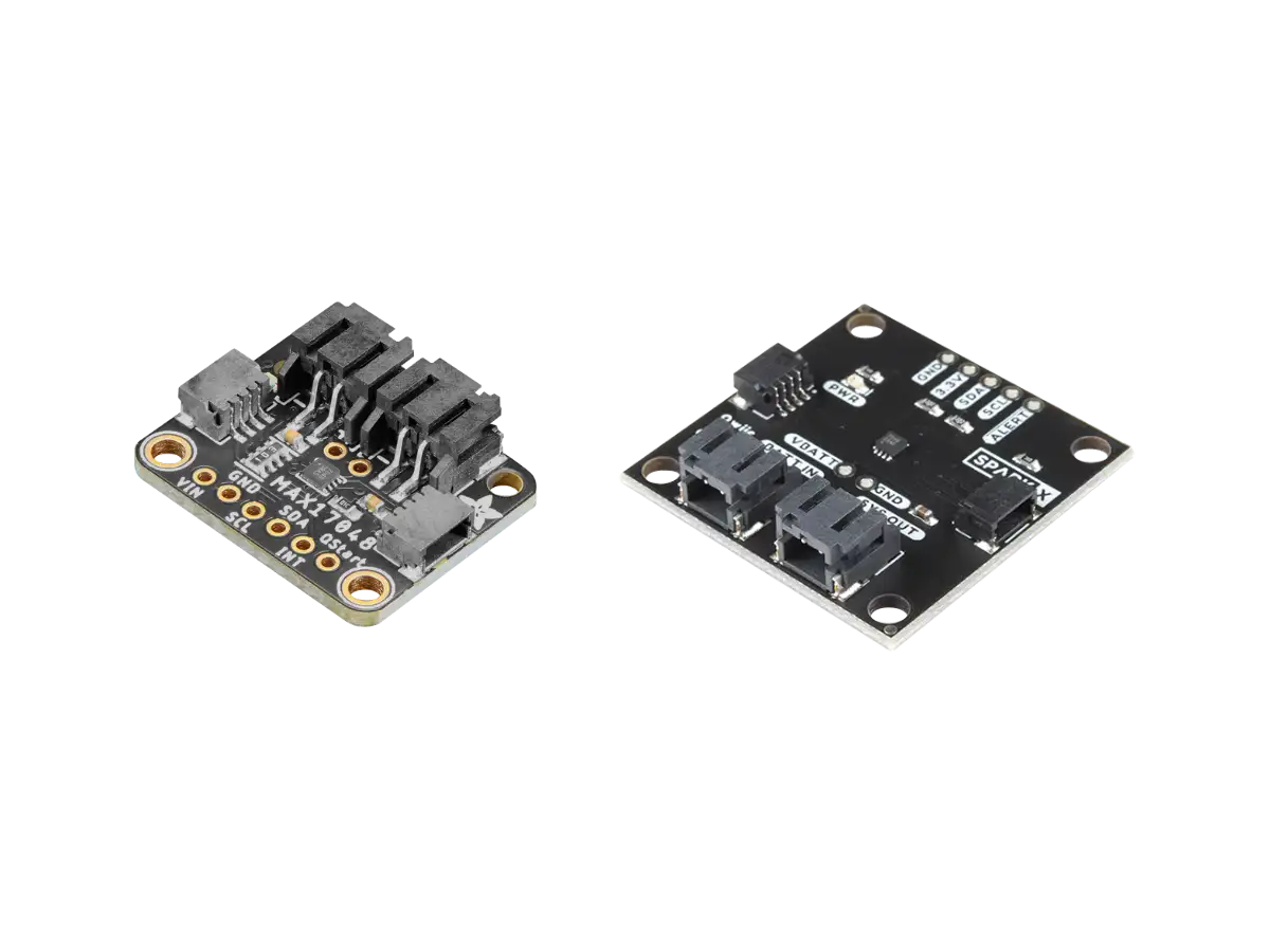
SparkFun MAX17043 Module
Overview
The SparkFun MAX17043 module (TOL-20680) shown in the figure below is a Battery Fuel Gauge that breaks out the MAX17043 IC.
The breakout board has the following features:
- 2-Pin JST 2.0PH connector for the battery with an input voltage range between 2.5V to 4.5V
- Battery pins broken out into pin through holes labeled as + and -
- 3-Pin through holes on each side of the board with 0.1" (2.54mm) spacing
- VCC pin with a voltage range of 3.0V to 5.5V that is connected to the I2C and alert pull-up resistors
- I2C pin through holes with two 2.2kΩ pull-up resistors connected to the SDA and SCL lines
- ALRT pin through hole
- QSTRT pin through hole with built-in 2.2kΩ resistor
- 3-Pad jumper on the back of the board that can be modified to use multiple devices on the I2C bus
The board operates with 3.3V or 5.0V for both power and communication, so it should work with any microcontroller or SBCSingle Board Computer with an I2C interface.
SparkFun has a Hookup Guide and software libraries available for Arduino to read the battery voltage and percentage. The hookup guide shows how to connect the fuel gauge to a microcontroller board while also powering the microcontroller board from the battery, and how to include a battery charging circuit.
Specs
| Parameter | Description |
|---|---|
| Main IC | MAX17043G+U by Maxim Integrated (a subsidiary of Analog Devices) |
| Interface |
|
| Accuracy |
|
| Operating Voltage | 3V to 5.5V DC via the VCC and GND pins |
| Power Consumption |
|
| Board Size | 24.13mm x 10.16mm (0.95in x 0.40in) |
Board Layout
The SparkFun MAX17043 board layout is given below. The board includes a 2-pin JST connector to hook up a single cell LiPo battery. As alternative to the JST connector, there are also PTHPin Through Holes labeled as + and - that you can solder the battery to. The following PTHs are also included on the board: VCC and GND for power, SCL and SDA for I2C communication, ALT pin for low battery alerts, and QST to reset the board.
On the back of the board there are three pads connected by a trace, labeled I2C, that can be modified if multiple devices are needed on the I2C bus.
| Pin | Function |
|---|---|
| Battery (+ -) |
The battery can either be connected to the JST 2.0PH port or to the + and - PTHs.
When using the + and - PTHs, be careful with the battery polarity. There is no protection diode on the board, so a reversed battery will damage it. The battery input voltage range is between 2.5V to 4.5V. Note that the nominal voltage of a single cell LiPo Battery is around 3.7V, but fully charged the voltage is at around 4.2V. This input also powers the IC and should be connected to your system's power input as well. |
| VCC | Power supply pin for the board between 3V-5.5V DC. Although the MAX17043 is powered by the connected battery, VCC determines the I2C logic levels. |
| GND | Common ground for power and logic. |
| SCL | This is the I2C clock pin SCL, connect to your microcontroller's I2C clock line. There's a 2.2kΩ on this pin. |
| SDA | This is the I2C data pin SDA, connect to your microcontroller's I2C data line. There's a 2.2kΩ pull-up on this pin. |
| ALT |
The ALT pin is the alert pin. The datasheet labels this as ALRT but SparkFun decided to label it as ALT due to
the size of the board.
This pin is active low indicating that there is a low state of charge. It can be connected to a microcontroller's interrupt pin or it can be left unconnected and the status can be viewed though I2C. |
| QST |
The QST pin is for quick-start input. The datasheet labels this pin as QSTRT but
SparkFun decided to label it as QST due to the size of the board. This allows users to reset the device through
hardware.
By default, the pin is connected to ground through a built-in 2.2kΩ resistor as suggested by the datasheet. A rising edge on this pin will initiate a hardware reset. One possible application is connecting this pin to a microcontrollers reset pin should users decide to initiate a hardware reset. A reset can also be initiated through software as well. |
|
3-Pad Jumper
(Backside) |
There are three pads connected by a trace on the back of the board, labeled I2C, that can be modified if multiple
devices are needed on the I2C bus.
The 2.2kΩ pull-up resistors are attached to the primary I2C bus; if multiple devices are connected to the bus with the pull-up resistors enabled, the parallel equivalent resistance will create too strong of a pull-up for the bus to operate correctly. As a general rule of thumb, disable all but one pair of pull-up resistors if multiple devices are connected to the bus. |
SparkFun has provided a schematic of the board on their website (Source PDF). This same schematic is shown below, but with dark themed colors.
DFRobot MAX17043 Module
Overview
The DFRobot MAX17043 module (DFR0563) shown in the figure below is another Battery Fuel Gauge that breaks out the MAX17043 IC.
The breakout board has the following features:
- 2-Pin JST 2.0PH connector for the battery with an input voltage range between 2.5V to 4.2V
- 2-Pin screw terminal to power an external device from the battery
- VCC pin with a voltage range of 3.3V to 6.0V
- 4-Pin GravityGravity connectors are DFRobot's name for 3 or 4 pin JST PH connectors with 2.0mm pitch. These connectors were implemented on DFRobot's boards to make it easy to plug-n-play various sensors and devices without soldering and wiring. The DFRobot Gravity connectors are cross-compatible with Seed Studio Grove and Adafruit’s STEMMA connectors. connector for I2C
- Low Battery Alert (ALR) and GND pin through holes
The board operates with 3.3V or 5.0V for both power and communication, so it should work with any microcontroller or ADCAnalog-to-Digital Converter (ADC, A/D, or A-to-D) with an I2C interface. DFRobot has a Product Wiki and software libraries available for Arduino to read the battery voltage and percentage. The Product Wiki shows how to connect the fuel gauge to a microcontroller board and a Raspberry Pi SBCSingle Board Computer, and also includes an application with a solar panel.
Specs
| Parameter | Description |
|---|---|
| Main IC | MAX17043G+U by Maxim Integrated (a subsidiary of Analog Devices) |
| Interface |
|
| Accuracy |
|
| Operating Voltage | 3.3V to 6V DC via the VCC (+) and GND (-) pins in the Gravity 4-pin connector |
| Power Consumption |
|
| Board Size | 22.0mm x 30.0mm (0.0.86in x 1.18in) |
Board Layout
The DFRobot MAX17043 board layout is given below. The board includes a 2-pin JST PH2.0 connector to hook up a single cell LiPo/Li-ion battery. A 2-pin screw terminal (green) is used to power an external device from the battery. To read the battery percentage data, the module is connected to a microcontroller or SBC using the 4-pin Gravity connector: I2C (SCL, SDA) pins and power (VCC, GND) pins.
An ALR pin through hole on the board can be used as a Low battery power alert interrupt (active low). The board also has a reverse battery LED indicator labeled REV LED: when the battery connection is reversed, the LED lights up.
DFRobot has provided a schematic of the board (Source PDF). This same schematic is shown below, but with dark themed colors.
Related Content

Products

Created:
10Dec2023 01:22:18 UTC
2023-12-10T01:22:18Z
Updated:
08May2024 00:30:38 UTC
2024-05-08T00:30:38Z
- Measures single cell Li-ion or LiPo battery percentage
- I2C Interface
- Supply Voltage: 3.3V to 5V
(0) Comments
Sign in to leave a comment
Sign In