AC Mains Voltage Detectors
Updated: 21Aug2024 00:17:28 UTC 2024-08-21T00:17:28Z
Rating: (0 reviewsThis article has not been rated yet)
The Mains AC 220V voltage detector can be used to detect when the power on a line from an outlet is turned on/off, such as lights, appliances, or determining when power outages occur.
The detector determines if 120V/220V AC power is supplied to the input terminals and outputs a lower voltage level digital on/off signal that can be read by microcontroller, SBC, or PLCProgrammable Logic Controller. The mains AC voltage detector modules are available in single channel or multiple channels.
This hardware overview of the AC Mains 220V Voltage Detector covers single and multi channel detector modules and how they work with board layout, pinout, and schematics.
Single Channel Module
Overview
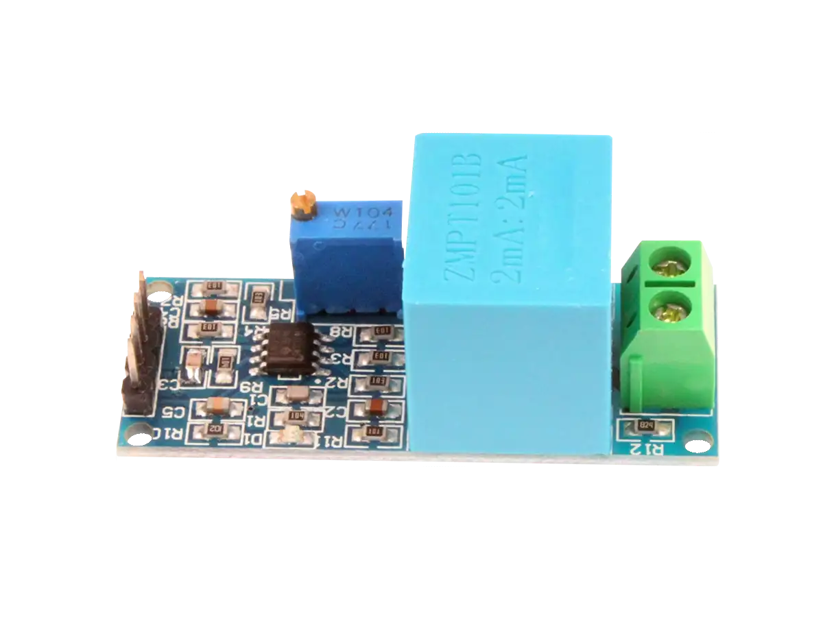
The single channel mains voltage detector module shown in the figure below determines if 120V/220V AC power is supplied to the 2 input screw terminals and outputs a digital TTL Level signal that can be read by microcontroller, SBCSingle Board Computer, or PLCProgrammable Logic Controller.
The output digital signal level has a high VCC and low 0V, where an on-board optocoupler ICIntegrated Circuit isolates the high mains voltage from the digital output. The power supply (VCC) for the module can be 3V to 5V or it can be connected to PLC 24V level. The board has a size of 73mm x 15mm (2.87in x 0.59in).
Board Layout
The inputs and outputs for this module are shown in the figure below. There are two screw terminals for the inputs: the AC power line (L) and the AC neutral line (N). On the other side of the board are three screw terminals for VCC, GND, and OUT.
| Pin | Function |
|---|---|
| AC Line (L) | Input hot line for AC voltage measured |
| AC Neutral (N) | Input neutral for AC voltage measured |
| VCC | 3V to 5V voltage supply for optocoupler and output |
| GND | Common ground for optocoupler and output |
| OUT | Output of voltage detection for microcontroller or other device. The high level is VCC and low level is 0V |
The large resistor on the board limits the current from the high input voltage applied and the rest of the circuit filters and detects the signal. The chip on the right side of the board is an optocoupler, powered by the VCC and GND terminals, which isolates the high input voltage from the output terminal. The board has a green power indicator LED that turns on when AC power is applied to the inputs L and N (it is not connected to VCC and GND).
The circuitry in white rectangle on the board, labeled High-Voltage, should not be touched during operation to avoid electrocution. This area of the board should also not touch any metal enclosure and it is recommended that you use nylon spacers to mount the board when using a metal enclosure.
A schematic for the board is shown below.
The large resistor of 150kΩ (R1) off the input line (L) terminal limits the current due to the large input voltage is applied. Then it passes through a full-wave bridge rectifier MB6M IC (D1) to remove the negative AC voltage. The positive signal is then filtered by a smoothing electrolytic capacitor of 100μF (C1).
The green Gallium Phosphide (GaP) LED (LED1) is used as a power indicator to let you know when the AC power line is inputting power. The output of power LED1 is fed into an optocoupler IC (U2) for isolating the high voltage AC circuit from the digital output. It is not clear why the 1N4148 diode D2 was added (let us know in the comments).
The output on the other side of the optocoupler is tied to a 47kΩ pull-up resistor to VCC (+5V). This means that when output side is conducting current, the output voltage is 0V. When there is no current conducting on the output side, the output voltage is VCC (+5V).
Inverting the Output
You could invert the output (+5V on, 0V off) by simply adding a diode or LED in parallel with the 47kΩ pull-up resistor (essentially bypassing it) and then connect a pull-down resistor on the ground terminal before connecting to ground. No soldering is needed with this fix since you are just connecting these extra components to the terminals and applying.
Multiple Channel Modules
The board shown so far only detects voltage on one input line (1 channel), but there are also 3 channel and 8 channel boards available (shown below). The VCC supply for both modules are 3V to 5V.
Related Content

Products

Created:
10Dec2023 04:14:13 UTC
2023-12-10T04:14:13Z
Updated:
08May2024 01:06:03 UTC
2024-05-08T01:06:03Z
- Detects 120V/220V AC
- Output TTL Level
- Supply Voltage: 3.3V to 5V
- 1/3/8 Channel Modules
(1) Comments
Sign in to leave a comment
Sign In
Please confirm the circuit, especially the position of the capacitor, when convenient;#https://www.instructables.com/AC-Mains-Detector-Circuit/
thanks.