LC709203F Battery Fuel Gauge
Updated: 19Aug2024 23:25:02 UTC 2024-08-19T23:25:02Z
Rating: (0 reviewsThis article has not been rated yet)
The LC709203F ICIntegrated Circuit by On Semiconductor (Onsemi) measures the voltage and charge percentage on a single cell LiPoLithium Polymer or Li-ionLithium-ion battery and accounts for the non-linear voltage behavior of the battery. This IC outputs the battery's voltage and percentage data over I2CInter-Integrated Circuit. Also referred to as IIC or I2C. and also has a separate alert output that tells you when the charge has dropped below a certain percentage.
This hardware overview of the LC709203F Fuel Gauge covers both the IC and the Adafruit Breakout Board Module, which has external circuitry, an onboard power LEDLight Emitting Diode, and two STEMMA QTSTEMMA QT ('cutie') connectors are Adafruit's name for 4-pin JST SH connectors with 1.0mm pitch. These connectors were implemented on Adafruit boards to make it easy to plug-n-play various sensors and devices without soldering and wiring. The STEMMA QT (JST SH) are a smaller connector than the STEMMA (JST PH) that do not fit on smaller boards. STEMMA QT is cross-compatible with SparkFun Qwiic connectors. (JSTJapan Solderless Terminal 2.0PH) connectors that makes the LC709203F easier to interface to.
The LC709203F IC reached its EOLEnd Of Life on 07Apr2021 and manufacturing of the chip is discontinued. Onsemi replaced the LC709203F with an upgraded version LC709204F (Onsemi LC709204F Product Page). The LC709204F has less power consumption and an improved algorithm for determining battery charge.
It is still worthwhile to cover the LC709203F IC because products that use this chip, like the Adafruit breakout, are still being sold and used.
LC709203F IC
Overview
The LC709203F ICIntegrated Circuit by On Semiconductor (Onsemi) is a Battery Fuel Gauge that measures the Relative State Of Charge (RSOCRelative State Of Charge) on a single cell Li-ionLithium-ion or LiPoLithium Polymer battery. The LC709203F outputs the battery's cell voltage and charge percentage between 0% (empty) and 100% (full charge) through an I2CInter-Integrated Circuit. Also referred to as IIC or I2C. interface.
This ICIntegrated Circuit uses an algorithm called HG-CVRHybrid Gauging by Current-Voltage Tracking with Internal Resistance (Hybrid Gauging by Current-Voltage Tracking with Internal Resistance) that accounts for the non-linear voltage behavior of the battery to get a valid percentage, even under unstable conditions (e.g., changes of battery, temperature, loading, aging, and self-discharge). The IC does not need the battery at full charge to calibrate and can even calibrate at half charge.
The LC709203F IC also features a low battery alarm interrupt, battery temperature input, and low power sleep mode.
- The low battery alarm interrupt can signal when the battery has a low voltage/percentage, where the threshold for this alarm is configurable over I2C.
- The battery temperature input is for batteries with an internal thermistor for more accuracy in determining the battery percentage and for reporting the temperature over I2C.
- The low power sleep mode is configurable over I2C with a normal active mode that draws 15μA (typical) to 26μA (max) and a sleep mode that only consumes 0.2μA (typical) to 4μA (max).
LC709203F Specs
| Feature | Description |
|---|---|
| IC Info |
On Semiconductor LC709203F Smart LiB Gauge Battery Fuel Gage LSILarge Scale Integration For
1-Cell Li-Ion/LiPo
|
| Input |
|
| Output |
|
| Accuracy | 2.8% accuracy of RSOC |
| Precision |
|
| Operating Voltage | The LC709203F IC is powered by the connected battery that can be between 2.5V to 4.5V DC. |
| Power Consumption |
|
| Package |
The IC is available in two packages:
|
| IC Size |
|
Pin Functions
The LC709203F comes in two different packages: WDFN8 and WLCSP9. The pin configuration for the WDFN8 package is given in the diagram below followed by a table defining each of the pins.
| Pin | Name | Function |
|---|---|---|
| 1 | TEST | Connect this pin to VSS. |
| 2 | VSS | Battery's negative (-) pin. |
| 3 | VDD | Battery's positive (+) pin. |
| 4 | ALARMB | This pin indicates alarm by low output (open drain). Pull-up must be implemented externally. Connect this pin to VSS when not in use. |
| 5 | TSW |
Thermistor Mode:
Power supply output for battery thermistor. This pin goes HIGH during temperature read operation. Resistance value of TSW (for thermistor pull-up) must be the same value as the thermistor. I2C Mode: Leave TSW disconnected when not using a battery thermistor. |
| 6 | TSENSE |
Thermistor Mode:
Thermistor sense input. If you connect this pin to thermistor, insert 100Ω resistance between them for ESD. I2C Mode: Leave TSENSE disconnected when not using a battery thermistor. In I2C mode, the temperature is provided by the host processor. |
| 7 | SDA | I2C Data pin (open drain). Pull-up must be done externally. |
| 8 | SCL | I2C Clock pin (open drain). Pull-up must be done externally. |
Function
The LC709203F measures battery voltage, temperature, internal impedance, and OCVOpen Circuit Voltage (Open Circuit Voltage, the battery voltage without load current). The battery current is calculated from the measured battery voltage, internal impedance, and OCV.
Information about how the internal impedance and OCV are affected by the remaining battery capacity, temperature, and more, is stored as a look up table in memory on the IC. The HG-CVRHybrid Gauging by Current-Voltage Tracking with Internal Resistance algorithm accumulates battery coulomb using the information of the current and a steady period by a high accuracy internal timer. The remaining capacity of a battery is calculated with the accumulated coulomb.
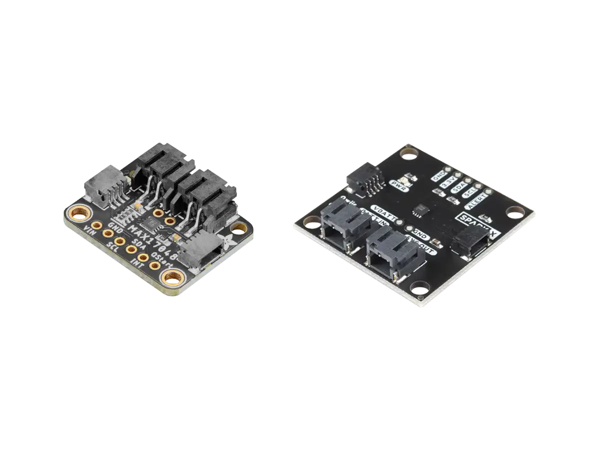
Adafruit LC709203F Module
Overview
The Adafruit LC709203F module (PID 4712) shown in the figure below is a Battery Fuel Gauge and Monitor based on the LC709203F IC by On Semiconductor (Onsemi) that measures the voltage and percentage (0% empty to 100% full charge) on a single cell Li-ionLithium-ion or LiPoLithium Polymer battery and decodes the non-linear voltage behavior of the battery to get a valid percentage.
The LC709203F IC has a non-linear voltage algorithm called HG-CVRHybrid Gauging by Current-Voltage Tracking with Internal Resistance, which provides an accurate RSOCRelative State Of Charge even under unstable conditions (e.g., changes in the battery due to temperature, loading, aging, and self-discharge).
This module outputs the battery's voltage and percentage data over I2CInter-Integrated Circuit. Also referred to as IIC or I2C. and operates with 3.3V or 5.0V for both power and communication, so it should work with any microcontroller or SBCSingle Board Computer with an I2C interface.
Adafruit has software libraries available for Arduino and CircuitPython/Python to read the battery voltage and percentage, where you can set the battery pack size to help tune the percentage calculation.
Specs
| Feature | Description |
|---|---|
| Main IC |
On Semiconductor LC709203F Smart LiB Gauge Battery Fuel Gage LSI For 1-Cell
Li-Ion/LiPo
|
| Interface |
|
| Accuracy |
|
| Operating Voltage | 3V to 5V DC with an on-board LED power indicator |
| Power Consumption |
|
| Board Size | 25.4mm x 20.3mm x 7.1mm (1.0in x 0.8in x 0.3in) |
Board Layout
The Adafruit LC709203F board layout is given below. There are two JSTJapan Solderless Terminal 2.0PH ports connected together at the top of the board, so you can connect the battery to one and a load/charger to the other (it doesn't matter which one). The power and I2C data lines can be connected to the STEMMA QTSTEMMA QT ('cutie') connectors are Adafruit's name for 4-pin JST SH connectors with 1.0mm pitch. These connectors were implemented on Adafruit boards to make it easy to plug-n-play various sensors and devices without soldering and wiring. The STEMMA QT (JST SH) are a smaller connector than the STEMMA (JST PH) that do not fit on smaller boards. STEMMA QT is cross-compatible with SparkFun Qwiic connectors. connectors on each side of the board (either one) or to the pins on the bottom of the board. There is an LEDLight Emitting Diode on the left side of the board to indicate when the board is powered.
On the back of the board there are two pads connected by a trace, labeled LED, shown in the figure below. If you want to conserve power when running only on battery, you can cut this trace to disable the LED on the breakout.
There are 6 PTHPin Through Holes on the bottom of the board that can be used for powering the board, I2C data communication, a low voltage/percentage alarm interrupt, and to measure the battery temperature (if the battery has a thermistor). Each of the pin functions are defined in the table below.
| Pin | Function |
|---|---|
| VIN | Power supply pin for the board between 3V-5V DC. The LC709203F is powered by the connected battery, not by VIN. The LC709203F will not respond to I2C scans or commands if the battery is not plugged in or too low. |
| GND | Common ground for power and logic. |
| SCL | This is the I2C clock pin SCL, connect to your microcontroller's I2C clock line. There's a 10K pullup on this pin. |
| SDA | This is the I2C data pin SDA, connect to your microcontroller's I2C data line. There's a 10K pullup on this pin. |
| STEMMA QT Ports |
These connectors allow you to connect to dev boards with STEMMA QT connectors. There are two of these ports on the sides of the board so you can connect your device (microcontroller, SBC, etc.) to either one of them. |
| JST Ports |
2x JST 2.0 PH connectors for the battery. There are two JST ports connected
together so you can connect the battery to one and a load/charger to the other.
Be careful with the battery polarity. There is no protection diode on the board, so a reversed battery will damage it. There are + and - symbols on the PCB to indicate polarity. |
| INT | Interrupt signal out, you can set this up to pull low when the voltage or percentage drops below a threshold. Pulled up to VIN with a 10K resistor. |
| Therm | Reads the battery pack's temperature for some batteries that have an internal thermistor and temperature output line (usually these batteries have three wires coming out: red for positive, black for ground, and white for temperature). |
|
LED Pads
(Backside) |
There are two pads connected by a trace on the back of the board, labeled LED. If you want to conserve power when running only on battery, you can cut this trace to disable the LED on the breakout. |
Adafruit has provided a schematic of the board on their website (Source). This same schematic is shown below, but with dark themed colors.
Adafruit Board Hookup
The hookup of the Adafruit LC709203F module to a microcontroller board or other device requires 3.3V to 5V power and two I2C data lines (SDA, SCL), which can be connected to either the STEMMA QT connector or the pin through holes. Both the SDA and SCL data lines have a 10kΩ pull-up on the module and have the same logic voltage level as the power provided. A 3.7V/4.2V LiPo/Li-ion battery is connected to one of the JST ports.
You can also add a battery charger module or circuit to the other JST port to charge the battery when the microcontroller is connected to a different power source than the battery.
Related Content

Products

Created:
10Dec2023 01:25:41 UTC
2023-12-10T01:25:41Z
Updated:
08May2024 00:11:53 UTC
2024-05-08T00:11:53Z
- Measures single cell Li-ion or LiPo battery percentage
- I2C Interface
- Supply Voltage: 3.3V to 5V
(0) Comments
Sign in to leave a comment
Sign In