Measuring Voltage
Updated: 04Aug2024 20:50:13 UTC 2024-08-04T20:50:13Z
Rating: (0 reviewsThis article has not been rated yet)
A Voltmeter (or Multimeter) is often used to measure voltage in electronic circuits to test or troubleshoot devices. If you want to include voltage measurements in your application, a handheld multimeter would not be suitable due to its large size, cost, power consumption, and most of them do not have a data logging feature.
Voltage measurements can be made with an ADCAnalog-to-Digital Converter (ADC, A/D, or A-to-D) in a microcontroller where the data can be transferred to a computer to be stored, processed, and visualized. This is useful for monitoring voltage from the analog output of sensors or the power voltage of devices. Performing voltage measurements for data acquisition requires some familiarity of what voltage is, different voltage sources, signals, grounding, and the difference between single-ended and differential voltage measurement methods.
Voltage
Voltage is the electrical potential difference between two points in an electric field that can make charges move in an electrical flow. Voltage can be produced in many different ways, such as the electrochemical processes in cells and batteries, the build-up of electric charge on a capacitor, electromotive-force from electromagnetic induction in a generator, pressure induced from the piezoelectric effect in vibration sensors, temperature induced from the thermoelectric effect in thermocouples, and light on photovoltic solar panels.
In the International System of Units (SIThe International System of Units (SI) is the modern form of the metric system and the world's most widely used system of measurement employed in science, technology, industry, and everyday commerce.), the derived unit for voltage is the Volt (V) named after Alessandro Volta (1745-1827), an Italian physicist who invented the electric battery. A Volt is the energy per unit charge in Joules per Coulomb. The amount of volts can be measured on circuit components, power supplies, sensors, and other electronic devices.
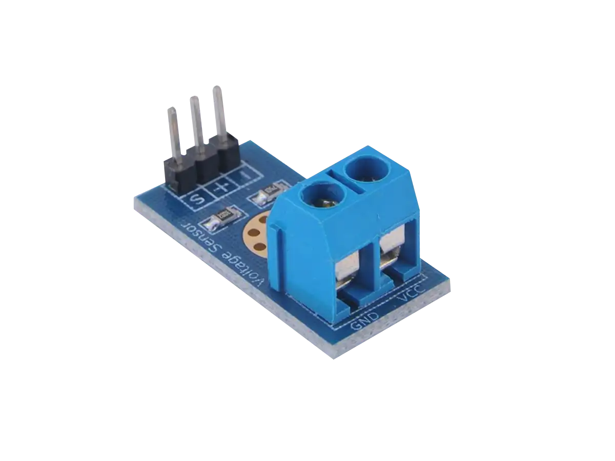
The power voltage on a device or load can be measured across its power terminals. If the power supply is a battery, measuring its voltage can be used to determine how much charge is left in the battery. Measuring the power voltage for devices can also be used to determine if there is sufficient voltage for the device to operate, too much voltage that can damage the device, or whether the voltage is stable enough for the device.
The voltage across electronic components within a circuit can also be measured to troubleshoot faulty components, identify bad connections, or understand the circuit design.
Many sensors provide an analog voltage output to quantify measurements of a different physical property, such as current, force (weight), temperature, pressure, and many other properties.
Voltage Signals
Direct Current (DC) and Alternating Current (AC) are two main types of signals that are have their own properties and are measured by different types of voltage sensors.
DC Voltage Signals
Direct Current (DC) signals are defined as a one directional flow of current in a circuit. A DC signal has only one electrical polarity of voltage and current, which are either constant, zero frequency, or variable with a slowly varying local mean value. Three examples of DC voltage signals are shown in the figure below.
AC Voltage Signals
Alternating Current (AC) signals are defined by a current flow that changes direction periodically. The voltage and current in an AC signal changes polarity and can be out of phase. The most basic type of AC signal is a sinusoidal waveform shown in the figure below.
An AC signal is characterized by its amplitude, period, frequency, phase, and DC offset.
- Amplitude:
- The height of the signal from a reference level such as zero.
- Period:
- The amount of time (T) the signal completes one cycle.
- Frequency:
- The number of repetitions (cycles) that occur in a specified amount of time, expressed in cycles/second or Hertz (Hz). A signal's frequency is inversely related its period: f = 1/T.
- Phase:
- The amount of horizontal shift relative to time zero, usually expressed in degrees or radians. A phase shift of 360 degrees (or 2π radians) gives the same wave with no shift.
- DC Offset:
- The amount of vertical shift in the waveform, where the waveform has DC and AC components as shown in the figure below.
Measurement Methods
Two common methods used for measuring voltages are Single-Ended and Differential measurement systems.
Single-Ended Measurements
Single-Ended voltage measurements have only one analog input channel making the measurement with respect to a common (ground) reference provided by either the device taking the measurement or by the external signal being measured. This method is used by ADCAnalog-to-Digital Converter (ADC, A/D, or A-to-D)s and microcontrollers that can read analog inputs when the input signal is high enough (usually greater than 1V) and the leads connecting the signal to the device are short (less than 10ft or 3m).
Differential Measurements
A differential voltage is the difference in voltage between two separate points in an electrical circuit. This method is useful for measuring voltages across a single component in a circuit. For example, to measure the voltage across a resistor, you measure the voltage at both ends of the resistor where the voltage difference is determined. Differential measurements are often made with an Instrumentation Amplifier (INAAn Instrumentation Amplifier (INA) is a type of differential amplifier in an IC that increases the disparity between its two inputs for amplifying a signal in measurements and test equipment.) that requires two inputs where neither input is referenced to the measurement system analog ground (AGND). This method is useful when the signal sources are low-level (less than 1V) where noise can be an issue or when the leads connecting the signal to the device are long (more than 10ft or 3m).
Ground References
Voltage measurements are relative, where one point must be compared to another point in the circuit. Ground (GND) is a reference point typically used as the base for all other voltage measurements within a circuit and can be 0V (not all voltage measurements are taken from this reference point, such as when measuring the voltage across a component). Ground references can provide a stable and fixed potential for measuring voltages or can act as a common return path for electric currents.
Ground is often the negative pole of the supply, but it could also be the positive pole of the supply or the mid point of a split supply. When measuring voltages there are different types of ground references to distinguish.
- Earth Ground:
- A direct physical connection to the Earth, often achieved through a grounding wire or a grounding strap. This is the most common type of common ground reference.
- Reference Point Ground:
- An arbitrary point in a circuit that is defined as the reference point, often used in electronic devices that don't plug into a wall socket, such as battery-powered devices.
- Common Ground:
- A reference point that is not necessarily connected to the Earth, but serves as a common return path for electric currents.
A common mistake when making single-ended voltage measurements is to have different power supplies on the signal source and measurement device where the grounds are not connected. This leads to questions on why the voltage measurement are close to 0V with random fluctuations in the readings.
The problem here is that the measurement circuit is open and no signal can flow into the measuring device because there is no return path. The open circuit probe acts like antenna that is prone to picking up electromagnetic noise and produces random voltage readings.
This problem can be resolved by providing a common ground connection between the signal source and measuring device. Now the signal has a complete circuit where it can flow into the measuring device and return along a path back to the power supply of the signal source.
Sometimes you don't want a common ground directly between the signal source and measuring device because you want to isolate the power supply of one from the other. Electrical isolation can be used to prevent ground loops, reject common-mode voltage, protect equipment, and provide safety when measuring high voltages (e.g., mains electricity at 120V/220V AC).
For isolation you need something that will pass the signal from one part to the other without any electrical connection. Common devices that can do this are transformers, relays, opto-isolators, magnetic isolators, and isolated amplifiers (e.g., ISO224). These devices are typically powered by the supply of the measuring device where the supply ground is used as the measurement ground reference.
Signal Sources
Before connecting a signal to the input of a measuring device you need to determine whether the signal source is floating or grounded.
Floating Signal Sources
A floating signal source has an isolated ground reference point, such as battery powered devices, thermocouples, opto-isolators, and isolation amplifiers. The ground reference of a floating signal must be connected to the ground of the device to establish a reference for the signal; otherwise, the measured input signal varies as the source floats outside the common-mode input range. You can measure floating signal sources with a Single-Ended measuring device as shown in the figure below.
For differential measurements you should include bias resistors from each lead, positive (+) and negative (-), to the instrument ground; otherwise, the measured signals can be unstable or at a positive or negative full-scale range of the instrument. Bias resistors provide a DC path from the inputs to ground of the instrumentation amplifier. The bias resistors should be small enough to keep the voltage within the range of the instrument and should be high enough not load the signal source and to allow the signal source to float with respect to the instrument reference. This typically results in bias resistors with a range of 10kΩ to 100kΩ.
Grounded Signal Sources
A grounded signal source is connected to a common ground point such as the outlet on a wall. If the measuring device and signal source are plugged into the same building power system, there can be a difference in ground potential between two instruments that is typically between 1mV and 100mV but can be higher. This potential difference causes an offset error in the measured voltage. This is known as a ground loop that occurs when two connected terminals in a circuit are at different ground potentials, causing current to flow between the two points.
A grounded signal source is more accurately measured with a differential measurement so the additional ground is not included in the measurement. Isolated measurements are another way to break ground loops.
Conclusion
This overview covered how to measure voltage within the limits of the test instrument, such as the range and resolution of an ADC. Measuring voltage outside these limits requires external circuitry that can attenuate, amplify, and/or offset the signal, which is covered in more detail in the Interfacing Analog Inputs article.
The precision and accuracy of voltage measurements with an ADC can be improved with calibration techniques or using an external precision reference voltage. How to do this depends on the measuring device and signal, but more details on the Arduino Uno R3 and Raspberry Pi Pico microcontroller boards for measuring DC voltages are available.
Related Content


Products


Created:
02Jun2024 06:17:36 UTC
2024-06-02T06:17:36Z
Updated:
02Jun2024 20:54:18 UTC
2024-06-02T20:54:18Z
- AD620
- AD623
- AD8221
- INA333
(0) Comments
Sign in to leave a comment
Sign In