Measuring DC Voltage with an Arduino Uno R3
Updated: 05Aug2024 01:10:15 UTC 2024-08-05T01:10:15Z
Rating: (0 reviewsThis article has not been rated yet)
This tutorial shows how to measure 0V to 5V DC voltage with the Arduino Uno R3 microcontroller board, including how to improve the precision and accuracy of DC voltage measurements by calibrating the Arduino ADCAnalog-to-Digital Converter (ADC, A/D, or A-to-D) or by using an external precision voltage reference.
ADC Inputs & AREF
The Arduino Uno R3 has 6 analog input pins (A0, A1, A2, A3, A4, A5) that can read analog signals between 0V and 5V into a 10-bit ADCAnalog-to-Digital Converter (ADC, A/D, or A-to-D) in the ATmega328P MCUMicrocontroller Unit. This converter scales an analog signal in a range of 0 to 1023, with a resolution between readings of 5 volts per 1024 units (4.9mV per unit). The Arduino Library analogRead() function takes about 100 microseconds to read an analog input, with a maximum reading rate of about 10,000 times a second.
The AREF pin is the Analog REFerence voltage for the ADC. When the ADC takes an analog reading, it compares it to the voltage at the AREF pin. The VREF voltage value is the full-scale value of the ADC (the maximum conversion value possible). For example, if you have a AREF set to 5V, then the input range of the ADC is 0V to 5V that gives count values from 0 to 1023. AREF is configured in software using the built-in alanogReference() function. For the Arduino Uno R3 there are three options to set as an argument to the alanogReference() function: alanogReference(DEFAULT), alanogReference(INTERNAL), and alanogReference(EXTERNAL).
- DEFAULT:
- The default analog reference of about 5V on the Arduino Uno R3. The default reference voltage is useful when measuring voltages that are directly dependent on the supply voltage. This default reference depends on your power supply voltage and stability, as well as the arduino board. Some power supplies and Uno boards have a protection diode that can drop VCCVoltage Collector Collector (VCC) is the supply voltage at the collector of a transistor. The double subscript notation of repeating letters "CC" is used to denote a power supply voltage that is relative to ground. to less than 4.5V.
- INTERNAL:
- A built-in reference equal to about 1.1V on the Arduino Uno R3 that is generated from the internal bandgap reference (VBG) through an internal amplifier. Since VREF is the full-scale value of the ADC, this means the input voltage range is limited to 0V to 1.1V (an input of 1.1V will give an ADC value of 1023). The accuracy of the internal reference is 1.1±0.1V and is stable, but slightly different for every single Arduino (not calibrated).
- EXTERNAL:
- An external voltage supply applied to the AREF pin (0 to 5V only) is used as the reference. A stable external voltage reference can be used to improve the resolution and accuracy of DC voltage measurements. Supplying a lower voltage than the 5V default can be used to reduce the input voltage range of the ADC closer to your measurement range to increase its resolution. A more precise voltage reference than the board supply can increase the accuracy of ADC voltage measurements.
Measuring DC Voltage
The Arduino Uno R3 can measure DC voltages between 0V and 5V with its analog pins. This could be a sensor or other voltage source such as a 1.5V AA battery, as long as its under 5V. For measuring external voltage sources, the positive voltage terminal is connected to the analog A0 pin and negative terminal to the GND pin (the source and Arduino must share a common ground).
The Arduino code sketch provided below makes voltage measurements on the A0 pin at a sampling interval of a half a second (500 milliseconds). It assumes the ADC is using a 5V voltage reference and converts the ADC counts between 0 and 1023 to 0V and 5V. The USB port on the Arduino Uno R3 board is connected to a computer to transfer the data serially and display the results on the Arduino IDEIntegrated Development Environment (IDE) is a software application that helps develop software code efficiently. console.
The output of measuring a AA battery, which has a nominal voltage of 1.5V, is provided below.
Calibration
AREF Calibration
The voltage on the AREF pin is used to convert the ADC count reading to a voltage according to the equation below.
In the previous sketch AREF was assumed to be 5.0V, but it can be slightly different (e.g., 4.95V) and cause errors in the ADC voltage measurements. Differences in the voltage reference mostly depend on the power source for the Arduino. By default AREF is supplied by the 5V system voltage of the Arduino Uno that comes from either a USB connection or from the onboard regulator using the DC power plug or Vin.
More accurate voltage measurements can be obtained by measuring the AREF pin with a Digital Voltmeter (DVMDigital Voltmeter) and using the measured value in your sketch when converting the ADC counts to volts. For example, the following sketch uses a measured voltage reference of 4.95V. If the Arduino power source changes by switching from USB to DC plug, battery, or even plugging the USB into a different computer, then the AREF pin needs to be remeasured.
Linear Calibration
The AREF calibration in the previous section is a single point calibration. The accuracy of Arduino voltage measurements can be further improved by calibrating the ADC with multiple samples across the range of your measurements. This can be achieved by changing the ADC input voltage with a variable power supply and measuring the voltages with both the ADC and a Digital Voltmeter (DVMDigital Voltmeter). A linear fit between the DVM measured voltages and ADC counts can be computed to determine the mapping between counts and volts given below. The slope of the linear fit is in Volts/Count and the offset should be a small value in Volts.
You can use the following sketch to obtain the ADC values in counts. This will output a sampling of the ADC counts every half second. Even with a stable input voltage, the ADC output may vary by a few counts due to noise. To reduce the error in the results due to noise you could average the samples.
An example of ADC readings from an input voltage between 0.5V and 4.5V in 0.5V steps is provided below. It is best not to take measurements close to the 0V and 5V limits of the ADC because most single ended ADCs have difficulty close to their power rails. You also don't want to risk damaging the Arduino by exceeding 5V due to noise or voltage spikes. Measuring too close to 0V will just include more quantization noise than desired into the calibration results.
| ADC Counts | Input Voltage |
|---|---|
| 103 | 0.51V |
| 210 | 1.04V |
| 312 | 1.53V |
| 428 | 2.07V |
| 520 | 2.54V |
| 632 | 3.08V |
| 726 | 3.52V |
| 831 | 4.03V |
| 942 | 4.56V |
A least squares Linear fit to the data determines the slope (4.8274 × 10⁻³ Volts/Count) and offset (2.0533 × 10⁻² Volts) calibration parameters. The Arduino sketch below shows how to use these parameters to convert ADC counts into voltage values.
External Reference Voltage
The AREF pin is the Analog REFerence voltage for the ADC where the voltage value is the full-scale value of the ADC (the maximum conversion value possible). The input range of the AREF pin is 0V to 5V DC.
Supplying a lower AREF voltage than the 5V default can be used to reduce the input voltage range of the ADC closer to your measurement range and improve its resolution (smaller voltage differences between digital steps). For example, if you wanted to use the ADC to monitor a signal that had a 0V to 3.3V range you could change the full-scale of the ADC by connecting AREF to a 3.3V source (or use the Arduino board regulated 3.3V pin), which will provide a resolution of 3.3V/1024 instead of 5.0V/1024. For the best results you should choose a reference that is just a little larger than the expected range of your measurements.
A stable and precise external voltage reference can also improve the accuracy of DC voltage measurements. The accuracy of the ADC is no better than the reference voltage AREF, where small variations in AREF become variations in the ADC reading. By default AREF is supplied by the 5V system voltage of the Arduino Uno that comes from either a USB connection or from the onboard regulator using the DC power plug or Vin. This means that the default voltage reference can be different depending on the power source, which can be a problem if the source changes.
One option is to use an external regulated power supply with a precise voltage output. The AREF input has a built-in resistance of 32kΩ according to the datasheet so a low impedance source is required if 10-Bit accuracy is to be obtained. If you are using an external power supply, be sure to connect the GND to the Arduino's GND pin.
Another option is to use the Arduino board 5V or 3.3V pins with a precision shunt voltage reference component. The LM4040 ICIntegrated Circuit is a common precision micropower shunt voltage reference chip that comes in fixed Reverse-Breakdown Voltages of 1.225V, 2.048V, 2.500V, 3.000V, 4.096V, and 5.000V. An example of how to hookup the LM4040 to the Arduino Uno R3 is shown in the figure below.
The external resistor by itself acts as a protection resistor that will alter the voltage that gets used as the reference because there is an internal resistor of about 32kΩ on the AREF pin. The two act as a voltage divider, so for example if the external resistor is 4.7kΩ then 5V applied through the resistor will yield 5V x 32kΩ / (32kΩ + 4.7kΩ ) ≈ 4.4V at the AREF pin. However, adding a precision shunt voltage reference between the divider and ground allows a small current to run through it to provide a stable and precise voltage known as its fixed reverse-breakdown voltage.
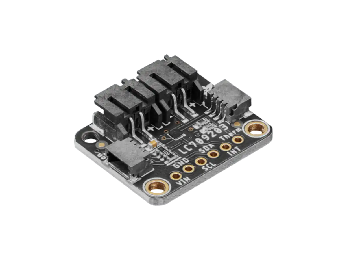
The LM4040 also comes in modules such as the Adafruit (PID 2200) breakout module shown below. This module comes with two different high precision shunt voltage references, 2.048V and 4.096V, with 0.1% accuracy. The 2.048V reference is useful for 3.3V microcontrollers, such as the RPi Pico and ESP32. The the 4.096V reference is used for 5V microcontrollers, such as the Arduino Uno R3. You can power the module with a supply between 5V and 12V, or 3V if you only want to use the 2.048V reference.
The figure below shows how to hookup the Adafruit LM4040 Module to the Arduino Uno R3. The supply voltage of the LM4040 module VIN is connected to the 5V output pin of the Arduino board. The LM4040 module and Arduino board need to share a common ground by connecting the GND pins. The 4.096V pin of the LM4040 module is the reference voltage connected to the AREF pin of the Arduino.
An example of an Arduino code sketch using the external LM4040 reference module is provided below. When using any external voltage as a reference make sure to set alanogReference(EXTERNAL) before calling analogRead(); otherwise it will short the active internal reference and the AREF pin, which may result in damaging the microcontroller.
Conclusion
This tutorial covered how to measure 0V to 5V DC voltage with the Arduino Uno R3 microcontroller board, and improving the precision and accuracy of measurements by calibrating the Arduino ADCAnalog-to-Digital Converter (ADC, A/D, or A-to-D) or by using an external precision voltage reference.
If you need to measure voltages above 5V, then you can to attenuate the signal with a voltage divider circuit or module. The Arduino ADC also has difficulty resolving small voltage signals around a few mV or less when using a 5V range and cannot measure negative voltages, but these signals can be amplified and/or shifted into the positive range with OpAmp circuitry. More details on attenuating, amplifying, and shifting signals are covered in the Interfacing Analog Inputs article.
Products
Created:
27Jul2023 18:12:25 UTC
2023-07-27T18:12:25Z
Updated:
03Sep2024 22:05:38 UTC
2024-09-03T22:05:38Z
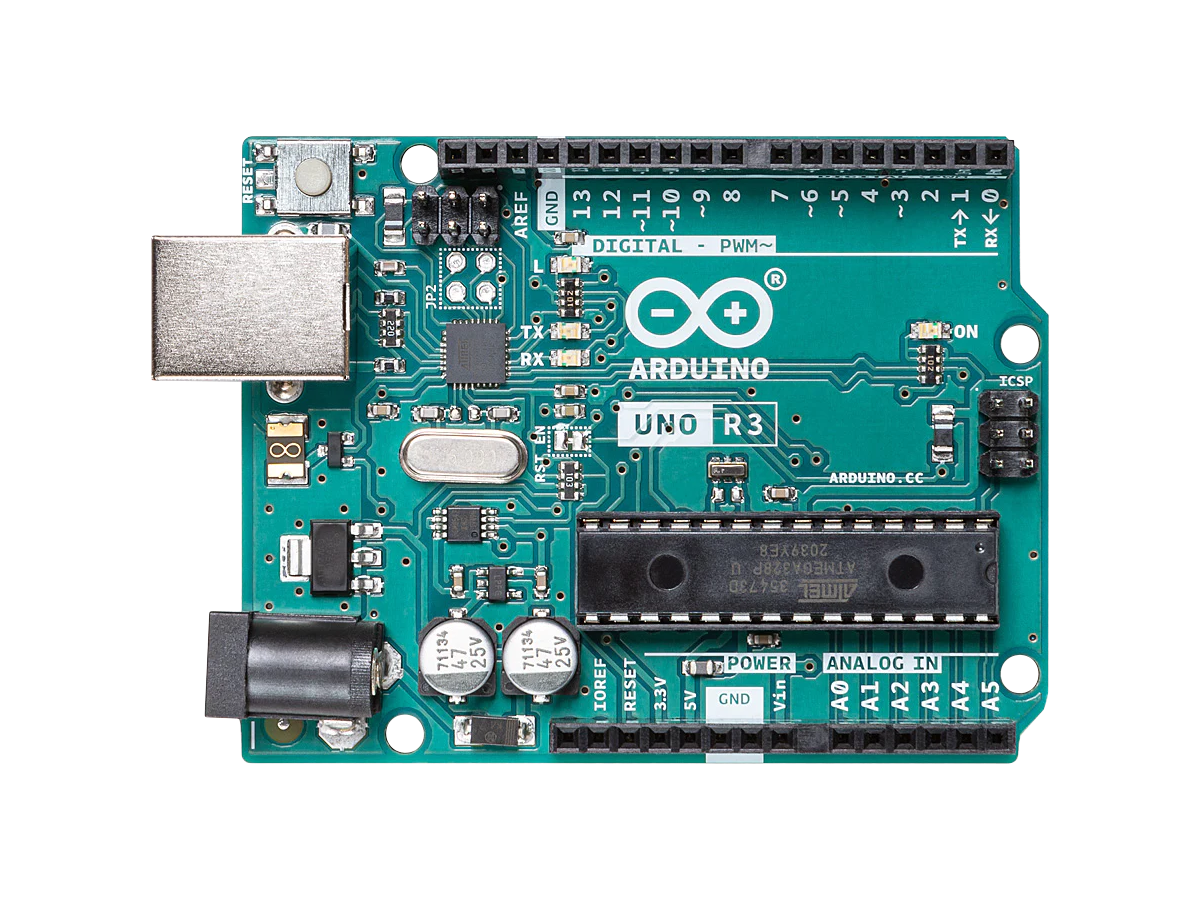
- Processor:
- 8-bit 16MHz AVRAVR microcontrollers derives its name from its developers and stands for, Alf-Egil Bogen and Vegard Wollan RISC microcontroller, and is also known as Advanced Virtual RISC. ATmega328P (max speed 20MHz)
- Memory:
- 32KB Flash, 1KB EEPROMElectrically Erasable Programmable Read-Only Memory, and 2048 bytes SRAMStatic Random Access Memory
- Interface:
- 14x Digital I/OInput/Output with 6x PWMPulse-Width Modulation, 8 channel 10-bit ADCAnalog-to-Digital Converter (ADC, A/D, or A-to-D), and UARTUniversal Asynchronous Receiver-Transmitter/I2CInter-Integrated Circuit. Also referred to as IIC or I2C./SPISerial Peripheral Interface
- Boards:
-
- Arduino Uno R3
- Compatible Boards: SparkFun Redboard, Adafruit Metro 328, Elegoo, SunFounder, DFRobot DFRduino
Created:
11Dec2022 19:49:54 UTC
2022-12-11T19:49:54Z
Updated:
04Sep2024 02:03:04 UTC
2024-09-04T02:03:04Z
- Processor:
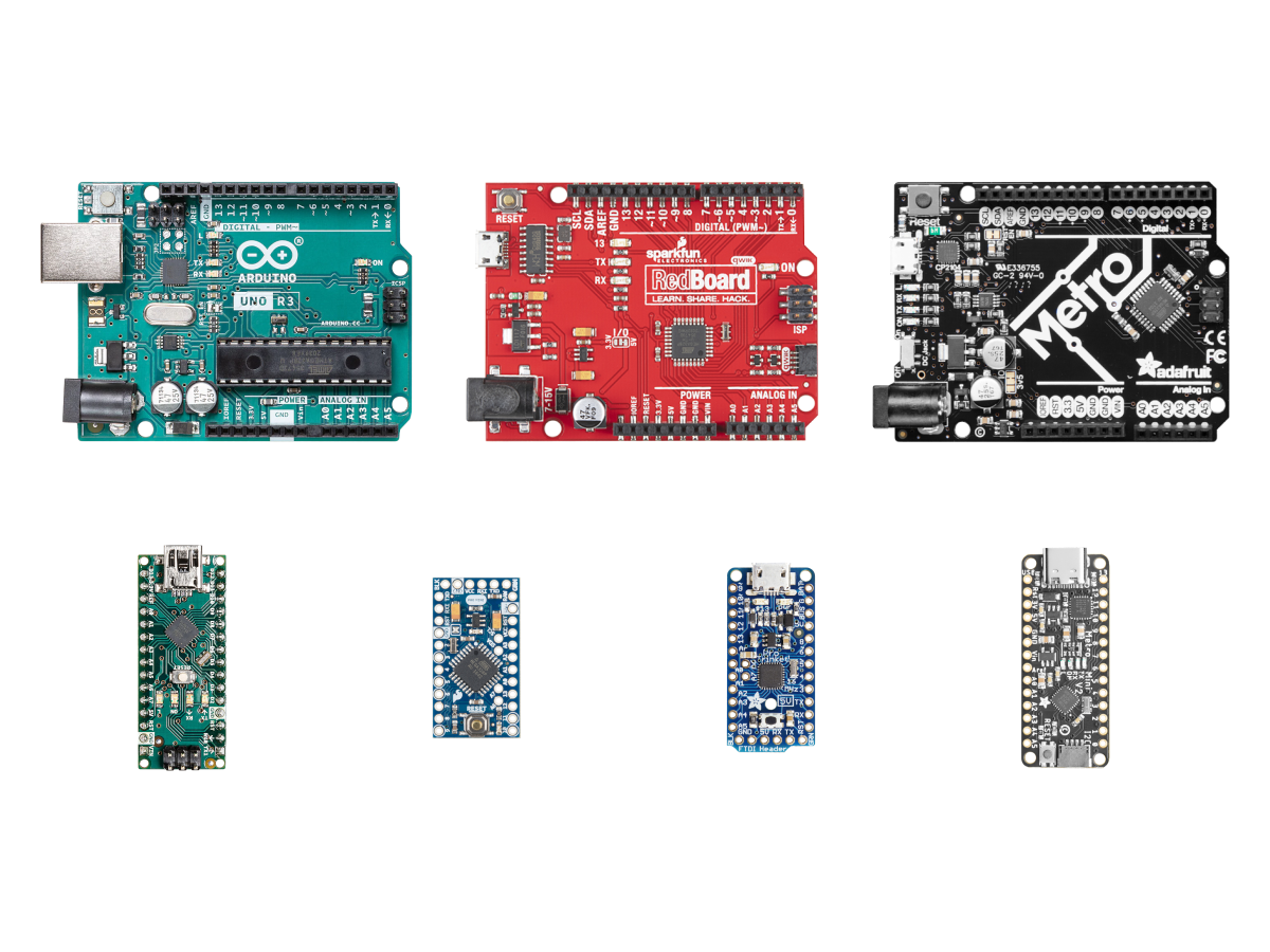
- 8-bit 16MHz AVRAVR microcontrollers derives its name from its developers and stands for, Alf-Egil Bogen and Vegard Wollan RISC microcontroller, and is also known as Advanced Virtual RISC. ATmega
- Memory:
- 32KB Flash, 1KB EEPROMElectrically Erasable Programmable Read-Only Memory, and 2048 bytes SRAMStatic Random Access Memory
- Interface:
- Up to 23x Digital I/OInput/Output with 6x PWMPulse-Width Modulation, 8 channel 10-bit ADCAnalog-to-Digital Converter (ADC, A/D, or A-to-D), and UARTUniversal Asynchronous Receiver-Transmitter/I2CInter-Integrated Circuit. Also referred to as IIC or I2C./SPISerial Peripheral Interface
- Boards:
-
- Arduino Uno R3, Nano, Pro Mini
- SparkFun RedBoard, Pro Mini
- Adafruit Pro Trinket, Metro, Metro Mini

Created:
26May2024 21:29:57 UTC
2024-05-26T21:29:57Z
Updated:
27May2024 03:59:16 UTC
2024-05-27T03:59:16Z
- LM4040 Modules
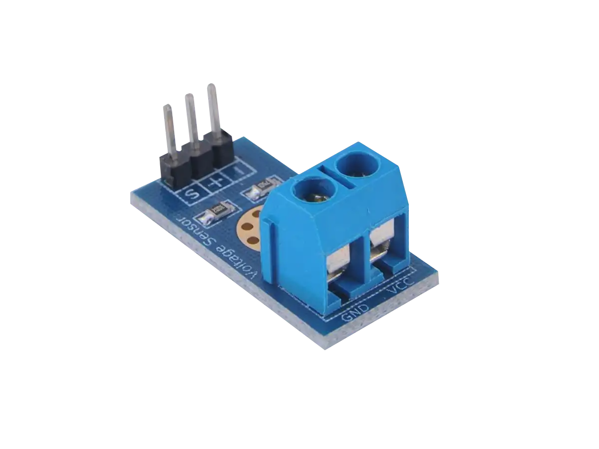
- AD584 Modules


(0) Comments
Sign in to leave a comment
Sign In