Single Board Computers (SBCs)
Updated: 16Aug2024 21:44:09 UTC 2024-08-16T21:44:09Z
Rating: (0 reviewsThis article has not been rated yet)
Single Board Computers (SBCSingle Board Computers) are complete computers built onto a single circuit board that includes a processor, memory, display ports, and input/output (I/OInput/Output) capabilities. SBCs are often used in applications where full-sized computer would be too expensive or unnecessary. They also tend to be more reliable, since they have fewer components that can fail. However, upgrading an SBC or adding more features is typically not feasible unless the entire board is replaced.
One of the key features of SBCs that makes them stand apart from microcontroller boards is the use of an operating system with the ability to run multiple software programs simultaneously. SBCs can perform basic computing tasks such as web browsing, word processing, and process audio and video. You can also create software that interacts with peripheral devices through a physical I/O interface called a GPIOGeneral Purpose Input Output. This makes SBCs popular as development boards that are used for designing custom software and hardware solutions.
This overview covers the common features of SBCs, such as processors, memory, communication interfaces, display ports, I/O, and power. Comparisons between different SBC boards will also be provided.
Usage
SBCSingle Board Computers are used in applications where space is limited, lower power consumption is needed, and/or lower cost is desired, compared to a full-sized desktop or laptop computer. Additionally, most SBCSingle Board Computers come with GPIOGeneral Purpose Input Output pins to directly interface to I/OInput/Output components such as switches, sensors, ADCAnalog-to-Digital Converter (ADC, A/D, or A-to-D)s, LCDLiquid Crystal Display/OLEDOrganic Light-Emitting Diode (OLED) displays, Relays, RTCReal-Time Clocks, Timers, IRInfrared remotes, RFRadio Frequency transceivers, etc. A few common applications of SBCs are described below.
- Home Automation:
- Using an SBC for controlling your smart home can offer a more open and privacy-minded approach than many commercial products. The SBC functions as the central hub, keeping track of the current state of your devices and communicating with them. You can create your own software or use free and open-source software such as Home Assistant.
- Home Security:
- Video surveillance, motion detectors, and door sensors can be processed by an SBC. A free open-source software application called MotionEyeOS can turn an SBC with a camera into a home video monitoring system. Photos and videos can either stay on the device, transferred to local storage on your network, or be uploaded to a cloud-storage service.
- Home Server:
- A home server is a computer that stores all of your digital files (including music, movies and photos) and shares them with the other computers in your home. It can also be used as a media server to stream media to other devices in your home, such as a Smart TV or a streaming media player.
- Network Attached Storage (NAS):
- A NAS is a file server that is connected to a network and allows multiple users to access its files. NAS devices are often used in small businesses or home offices, as they provide an inexpensive way to share files between multiple computers.
- Media Center:
- A media center allows you to play music and videos through your SBC onto a TV. The advantages of a SBC with this application is it can be left on 24/7 with low power consumption and all the software can be configured and modified in whatever way you want.
- Data Acquisition:
- An SBC can be used to collect and analyze data from various sensors. Many SBCs do not have an internal ADC, but an external ADC can be connected to the GPIO (I2C/SPI) of an SBC. There are also data acquisition HATs available for some SBCs.
Some other applications of SBCs are
- Web Server
- Streaming Server
- Email Server
- Weather Station
- Robot Controller
- GPS Tracker
- Time-lapse Photography
- Retro Gaming
SBC vs MCU
Processing Power
SBCSingle Board Computers and microcontrollers (MCUMicrocontroller Units) are both embedded systems that have processors and memory to execute programs with an I/O interface that you can access through software. However, SBCs have a lot more processing power and memory than microcontrollers in order to run an operating system (typically Linux or Windows) with multiple software applications running simultaneously to perform basic computing tasks such as web browsing, word processing, audio and video, with peripherals such as a mouse, keyboard, monitor, and speakers.
A microcontroller does not run an operating system and only execute a single program that is coded, compiled, and uploaded to the microcontroller. In general MCUs use less resources than an SBC, where the processing speed, RAMRandom Access Memory, and power consumption on an MCU is much lower than a SBC.
Interfaces
SBCs provide standard consumer-oriented computer interfaces like HDMIHigh-Definition Multimedia Interface, USBUniversal Serial Bus, Wifi, and Bluetooth. The operating system system is typically ran from external media such as a microSDThe microSD is a Secure Digital (SD) removable miniaturized flash memory card that is the compact version of a standard SD card and is meant to be used with smaller devices. card, eMMCEmbedded Multimedia Card module, flash drive, hard drives, and solid-state drives (SSDs), where data from applications can also be stored.
Both SBCs and MCUs typically have a GPIO. The main differences is that while almost all microcontrollers have analog inputs with an onboard ADCAnalog-to-Digital Converter (ADC, A/D, or A-to-D) and some have a DACDigital-to-Analog Converter (DAC, D/A, or D-to-A), SBCs usually do not have any analog inputs/outputs with a few exceptions (e.g., the BeagleBone Black has an ADC, but no DAC).
Timing
A microcontroller reads, writes, and processes data in real-time to interact with external devices such as sensors, motors, etc. If precise and accurate timing is critical to your application, then a microcontroller would be more suitable. Computers running an operating systems that manages and prioritizes software tasks can interfere with a process and make its timing accuracy less reliable.
Cost
Microcontrollers are much less expensive than SBCs. On the lower end, microcontrollers cost $5 to $10 USD, whereas a low end SBC would be around $50 to $100 USD: an order of magnitude difference in terms of cost.
Form Factor
SBCs come in many different sizes and this is an important factor to consider when purchasing a board, especially if there is limited in space for your application.
Below is a list of the PCB board sizes found on common SBCs. These sizes range from the smallest in the PocketBeagle and RPi Zero 2 W to the largest with the RockPro64, BeagleBone AI-64, and radxa Rock 5B.
| SBC | Dimensions (LxW) |
|---|---|
| RPi5 | 85mm x 56mm (3.35in x 2.21in) |
| RPi4B | 85mm x 56mm (3.35in x 2.21in) |
| RPi Zero 2 W | 65mm x 30mm (2.56in x 1.18in) |
| BeagleBone AI-64 | 102.5mm x 80mm (4.04in x 3.15in) |
| BeagleBone Black | 86.36mm x 53.34mm (3.40in x 2.15in) |
| BeagleBone PocketBeagle | 55.0mm x 35.0mm (2.2in x 1.4in) |
| Pine64 RockPro64 | 133mm x 80mm (5.24in x 3.15in) |
| Odroid N2+ | 90mm x 90mm (3.54in x 3.54) |
| Odroid C4+ | 85mm x 56mm (3.35in x 2.21in) |
| Orange Pi 5/5B | 100mm x 62mm (3.94in x 2.44mm) |
| Orange Pi 4 LTS | 91mm x 56mm (3.58 x 2.21in) |
| Orange Pi 3 LTS | 85mm x 56mm (3.35in x 2.21in) |
| Orange Pi Zero 2 | 60mm x 53mm (2.36in x 2.09in) |
| radxa Rock 5B | 100.15mm x 74.25mm (3.94in x 2.92in) |
| radxa Rock 4C+ | 85mm x 54mm (3.35in x 2.13in) |
| Libre Renegade | 85mm x 56mm (3.35in x 2.21in) |
Processors
The processors of a SBC are integrated into a single ICIntegrated Circuit called a System On a Chip (SoCSystem On a Chip) that takes up less space and uses less power than the multi-chip counterparts seen in full sized computers.
An SoC includes both the Central Processing Unit (CPUCentral Processing Unit) and a Graphics Processing Unit (GPUGraphics Processing Unit), each with their own memory used as registers for their operation. The CPU performs operations such as basic arithmetic, logic, controlling, and I/OInput/Output, while the GPU is used for handling multimedia tasks such as video, digital image processing, drawing 3D graphics, and playing games.
The SoC may also contain other processors such as PRUProgrammable Real-time Units and DSPDigital Signal Processors, as in the BeagleBone Black and BeagleBone AI-64 SBCs.
The SoC on an SBC contains the peripherals for communication and I/O interfacing. The most common ones are described below.
- Timers:
- Allows software to be time-dependent for scheduling and synchronizing.
- Interrupt Controller:
- Allows the OSOperating System to handle all the computer resources, both internally to the SoCSystem On a Chip and externally (e.g., I/OInput/Output devices), and determine when the CPUCentral Processing Unit is ready for new instructions.
- GPIOGeneral Purpose Input Output:
- Enables control of connections, input, output, and different modes of the GPIO pins.
- USBUniversal Serial Bus:
- Controls the services and provides protocols for data I/OInput/Output, allowing peripherals to communicate with the SBC.
- PCMPulse-Code Modulation / I2SInter-IC Sound:
- PCM is a digital representation of an audio signal and converts digital sound data to analog signals needed for speakers and headphones. I2S is an electrical serial interface used to transmit PCM data from when connecting audio devices.
- DMADirect Memory Access Controller:
- Direct Memory Access that allows an I/OInput/Output device to bypass the CPUCentral Processing Unit and send/receive data directly to the main system memory for speed and efficiency.
- I2CInter-Integrated Circuit. Also referred to as IIC or I2C. Masters:
- Inter-Integrated Circuit (I2C) used for communicating with lower-speed peripheral devices like sensors and microcontrollers.
- SPISerial Peripheral Interface Masters:
- Serial Peripheral Interface (SPI) used for communicating with higher-speed peripheral devices and allowing the daisy chaining of devices.
- UARTUniversal Asynchronous Receiver-Transmitters:
- Universal Asynchronous Receiver-Transmitter (UART) used for serial communication between different devices.
- PWMPulse-Width Modulation:
- Pulse-Width Modulation used to generate pulses with a specified duty cycle to control the brightness of LEDLight Emitting Diodes, control motors, and can provide limited analog-like output.
There are variety of SoCs with different manufacturers, such as Broadcom for the Raspberry Pi, Texas Instruments for BeagleBone, Rockchip for Pine64/Orange Pi/Libre, Allwinner for Orange Pi, and Amlogic for Odroid. The table below lists the SoCs on common SBCs.
| SBC | SoC |
|---|---|
| RPi5 |
Broadcom BCM2712 SoC
|
| RPi4B |
Broadcom BCM2711 SoC
|
| RPi Zero 2 W |
Broadcom BCM2710A1 SoC
|
| BeagleBone AI-64 |
Texas Instruments J721E-family TDA4VM SoC
|
| BeagleBone Black |
Texas Instruments Sitara AM3358BZCZ100 SoC
|
| BeagleBone PocketBeagle |
Octavo Systems OSD3358 SiPSystem-in-Package
|
| Pine64 RockPro64 |
Rockchip RK3399 SoC
|
| Odroid N2+ |
Amlogic S922X SoC
|
| Odroid C4+ |
Amlogic S905X3 SoC
|
| Orange Pi 5/5B |
Rockchip RK3588S SoC
|
| Orange Pi 4 LTS |
Rockchip RK3399 @ 1.8GHz (4GB) or RK3399-T @ 1.6GHz (3GB) SoC
|
| Orange Pi 3 LTS |
Allwinner H6 SoC
|
| Orange Pi Zero 2 |
Allwinner H616 SoC
|
| radxa Rock 5B |
Rockchip RK3588 SoC
|
| radxa Rock 4C+ |
Rockchip RK3399-T SoC
|
| Libre Renegade |
Rockchip RK3328 SoC
|
CPU
The Central Processing Unit (CPUCentral Processing Unit) is the most important component in a computer that acts as the "control center". It is a complex set of electronic circuitry that runs the machine's operating system and applications by executing instructions, arithmetic, logic, controlling, and I/O operations.
Different SBC boards have range of CPU performance that vary in the number of cores and clock speeds. Most SBCs have one core on the low end and up to eight cores on the high end. The CPU clock speeds range from 1GHz on the smaller boards such as the RPi Zero, PocketBeagle, and Orange Pi Zero 2, and up to 1.5GHz - 2GHz on the higher end performance boards such as the RPi4B, BeagleBone AI-64, Odroid N2+, Orange Pi 5, and radxa Rock 5B.
GPU
A Graphical Processing Unit (GPUGraphics Processing Unit) is designed for accelerating the rendering of graphics with parallel processing, including multimedia tasks such as video, digital image processing, drawing 3D graphics, and playing games. GPUs can also be used beyond graphics to accelerate high performance computing (HPC), deep learning, and more.
There are several companies that provide GPUs: Arm Holdings (Mali GPU), Imagination Technologies (PowerVR GPU), Broadcom (VideoCore GPU), Vivante, and Nvidia. The naming convention of the GPU can also vary slightly by different manufacturers. For example, the 4 core Arm Mali-T860 GPU in the Pine64 RockPro64 and Orange Pi 4 LTS SBCs may be designated Mali-T864: Arm's official name for this would be "Mali-T860 MP4", but some chip manufactures use the short-hand Mali-T864 name.
GPUs from different manufacturers have a lot of technical specifications that determine its performance, but the few described below are sometimes provided by the product pages of SBCs.
- GPU Core Clock Speed (MHz):
- The core clock speed is the frequency at which the GPU is running and indicates the number of computations the cores do every second, typically measured in MHz. All things being equal, higher clock speed will generally indicate better performance. However, the clock speed is not necessarily constant where there could be a base frequency that indicates the minimum stable clock speed of the processing core and the boost frequency as the upper frequency limit during heavy work load. Furthermore, many GPUs also support overclocking that allows increasing the frequency higher than the specs.
- GPU Core Processing (GFLOPSGiga (one billion) FLoating point Operations Per Second):
- The core processing floating point operations per second (FLOPSFLoating point Operations Per Second) is a metric that indicates the number crunching ability of a graphics processor (in the same way that a million instructions per second (MIPSMega (Million) Instructions Per Second) shows what a CPU can deliver). GPUs on SBCs typically have a range of 10GFLOPSGiga (one billion) FLoating point Operations Per Second up to 100GFLOPSGiga (one billion) FLoating point Operations Per Second. The GPUs in SBCs have much lower performance than a full sized PC graphics cards that contain GPUs with an order of magnitude more FLOPS with over 1TFLOPSTera (one trillion) FLoating point Operations Per Second (1 trillion floating point operations per second) of 32-bit floating point performance.
- GPU Pixel Fillrate (GP/sGiga (one billion) Pixels per second):
- The pixel fillrate is the number of pixels a GPU can render to the screen every second, typically measured in GP/sGiga (one billion) Pixels per second (1 billion pixels per second). Greater pixel fillrates provide higher screen resolution for the GPU. If you are looking for an easy top level requirement calculation, the following formula gives you the pixels per second: screen resolution x fps = pixels/sec.
- GPU Texture Fillrate (GP/sGiga (one billion) Pixels per second):
- Texture fillrate refers to the number of texture map elements (texels) the GPU can map to pixels in one second. The process of drawing pixels to the screen and applying the appropriate textures to them is called texture mapping: to render a 3D scene, textures are mapped over the top of polygon meshes which is accomplished by texture mapping units (TMUs) on the GPU. Texture fill rate is a measure of the speed with which a particular GPU can perform texture mapping: higher texture fillrates provide faster video displays fluently.
PRU
The Programmable Real-time Unit and Industrial Communications Subsystem (PRU-ICSSProgrammable Real-time Unit and Industrial Communication SubSystem / PRU-ICSSGProgrammable Real-time Unit and Industrial Communication SubSystem - Gigabit) is a small microcontroller (MCUMicrocontroller Unit) processor that is tightly integrated with an I/O subsystem, offering low-latency control of I/O pins on SoC devices. A PRUProgrammable Real-time Unit has its own execution core and memory with a rich instruction set.
A computer time-sharing operating system, such as Linux and Windows, manages the sharing of system resources with a scheduler, data buffers, or fixed task prioritization in a multitasking environment. These operating systems are unsuited to critical hard real-time tasks with response requirements shorter than a millisecond while providing general purpose computer tasks such as web browsing, word processing, file system support, etc.
By using a PRU, you can achieve fast, deterministic, real-time control of I/OInput/Output pins and devices without bottlenecking the CPU. It can trigger or receive interrupts, accesses the PWMPulse-Width Modulations, read ADCAnalog-to-Digital Converter (ADC, A/D, or A-to-D)s values, or access the main memory for sharing with the CPU.
DSP
A Digital Signal Processor (DSPDigital Signal Processor) is a specialized microprocessor ICIntegrated Circuit with an architecture optimized for processing digital signal data streams, such as audio, at high speed and low energy consumption. DSPs are quite common in consumer electronic devices such as headphones, smartphones, HDTV, and much more. They perform a large number of mathematical operations quickly and repeatedly on a series of data samples, such as codec encoding, filtering, and Fourier Transforms.
The advantage of having DSPs in an SBC is the CPU can offload data stream processing to the DSP where it runs more efficiently, while also not being a burden on the CPU that would slow down the system. DSPs have memory architectures that are optimized for ordered data streams and are typically built to run a number of operations in parallel for much faster processing with lower clock speeds than a CPU.
Memory
SBCs contain volatile memory, such as RAMRandom Access Memory, and non-volatile memory, such flash (eMMCEmbedded Multimedia Card) and microSDThe microSD is a Secure Digital (SD) removable miniaturized flash memory card that is the compact version of a standard SD card and is meant to be used with smaller devices. cards. The contents of volatile memory are lost if the board loses power, whereas the contents of non-volatile memory persists between power cycles.
- RAM:
- Random Access Memory (RAMRandom Access Memory) is volatile memory that is the temporary working data space for applications to store and access transient data. Having more RAM means that more data can be accessed and read faster than being written to flash, microSDThe microSD is a Secure Digital (SD) removable miniaturized flash memory card that is the compact version of a standard SD card and is meant to be used with smaller devices., or hard drive. RAM allows the SBC to perform most of its everyday computer tasks, such as loading applications, web browsing, word processing, and graphics. DDRDouble Data Rate (DDR) is a type of SDRAM memory that fetches data on both the leading edge and the falling edge of the clock signal that regulates it. and LPDDRLow-Power Double Data Rate are the two main types of SDRAMSynchronous Dynamic Random-Access Memory found on most SBCs. Each generation of DDR (DDR1, DDR2, DDR3, etc.) and LPDDR (LPDDR1, LPDDR2, LPDDR3) offers higher transfer rates and power efficiency.
- Storage:
- Flash and microSDThe microSD is a Secure Digital (SD) removable miniaturized flash memory card that is the compact version of a standard SD card and is meant to be used with smaller devices. cards are the non-volatile memory used by SBCs to store long term data, such as the operating system and files. It can be read, erased, and written to. The types of storage found on most SBCs are either onboard SPISerial Peripheral Interface flash or eMMCEmbedded Multimedia Card, a microSD card slot, or a connector for an external eMMCEmbedded Multimedia Card memory module.
| SBC | RAM | Storage |
|---|---|---|
| RPi5 | 4GB/8GB LPDDR4 |
|
| RPi4B | 2GB/4GB/8GB LPDDR4 |
|
| RPi Zero 2 W | 512MB LPDDR2 |
|
| BeagleBone Black | 512MB DDR3 |
|
| BeagleBone AI-64 | 4GB LPDDR4 |
|
| BeagleBone PocketBeagle |
512MB DDR3 |
|
| Pine64 RockPro64 | 4GB LPDDR4 |
|
| Odroid N2+ | 2GB/4GB DDR4 |
|
| Odroid C4+ | 4GB DDR4 |
|
| Orange Pi 5 | 4GB/8GB/16GB/32GB LPDDR4 |
|
| Orange Pi 4 LTS | 3GB/4GB LPDDR4 |
|
| Orange Pi 3 LTS | 2GB LPDDR3 |
|
| Orange Pi Zero 2 |
512MB/1GB DDR3
(shared with GPU) |
|
| radxa Rock 5B | 4GB/8GB/1GB LPDDR4 |
|
| radxa Rock 4C+ | 1GB/2GB/4GB LPDDR4 |
|
| Libre Renegade | 2GB/4GB DDR4 |
|
USB
USBUniversal Serial Bus ports are standard on almost all SBCs in order to connect peripherals such as a keyboard and mouse. The USB electrical lines communicate data and supply power to peripherals. The most common USB connectors on SBCs being female Type-A, Micro-B, and Type-C.
SBCs have different versions of USB that that determine the maximum data transfer rate and cable length (the maximum cable length depends on the USB speed). The table below lists the USB versions commonly found in SBCs. There are higher USB versions (e.g., USB 3.2, USB4, and USB4 V2.0) available for modern desktop and laptop computers, but are typically not implemented in SBCs yet as of this writing.
| SBC | Max Data Rate | Max Cable Length |
|---|---|---|
| USB 1.0 | Low-Speed: 1.5 MbpsMegabits per second | 3m (9.8ft) |
| USB 1.1 | Full-Speed: 12 MbpsMegabits per second | 5m (16.4ft) |
| USB 2.0 | High-Speed: 480 MbpsMegabits per second | 10m (32.8ft) |
| USB 3.0 | SuperSpeed: 5 GbpsGigabits per second | 5m (16.4ft) |
| USB 3.1 | SuperSpeed: 10 GbpsGigabits per second | 5m (16.4ft) |
When connecting devices with different USB versions, the data transfer rate will be limited by the slowest of the connected devices. For example, if you connect a High-Speed USB 2.0 device to a Low-Speed USB 1.1 device, the data transfer will be Low-Speed.
Some SBCs offer USB On-The-Go (OTGUSB On-The-Go (OTG) is a specification built into the USB port that allows devices to act as a host to control and power external devices or act as a peripheral.) ports, which is a specification built into the USB port that allows devices to act as a host to control and power external devices or act as a peripheral. SBCs with USB OTG can switch back and forth between the roles of host and device, where it can be a host to peripherals such as a mouse and keyboard or be seen as a device by host computer.
The table below lists the USB ports on different SBCs for data transfer with peripherals or host devices (SBC board power only connectors are not included). The most common USB connectors on SBCs are female Type-A, Micro-B, and Type-C, with USB versions 2.0 and 3.0.
| SBC | USB Ports |
|---|---|
| RPi5 |
|
| RPi4B |
|
| RPi Zero 2 W |
|
| BeagleBone Black |
|
| BeagleBone AI-64 |
|
| BeagleBone PocketBeagle |
|
| Pine64 RockPro64 |
|
| Odroid N2+ |
|
| Odroid C4+ |
|
| Orange Pi 5 |
|
| Orange Pi 4 LTS |
|
| Orange Pi 3 LTS |
|
| Orange Pi Zero 2 |
|
| radxa Rock 5B |
|
| radxa Rock 4C+ |
|
| Libre Renegade |
|
Ethernet
An Ethernet port is a hardware interface that connects a computer to a network. Ethernet is capable of transmitting large amounts of data at high speed, can accommodate multiple transmission data rates, and provides a stronger signal over a longer distance compared with a USBUniversal Serial Bus cable (e.g., Cat5, Cat5e, and Cat6 Ethernet cables can go up to 100m or 328ft in length before signal attenuation occurs).
Ethernet can be used to connect to the Internet, a Local Area Network (LANLocal Area Network), or a Wide Area Network (WANWide Area Network). You can also use Ethernet to connect an SBC to video cameras or to your home modem/router to monitor internet speeds.
Ethernet ports come in different speeds with the two most common speed standards for computers being 10/100 and 10/100/1000 developed by the Institute of Electrical and Electronics Engineers (IEEEInstitute of Electrical and Electronics Engineers (Industry Standards)). A 10/100 Ethernet connection is capable of transferring data at either 10MbpsMegabits per second or 100MbpsMegabits per second. A 10/100/1000 Ethernet, also referred to as Gigabit Ethernet or GbEGigabit Ethernet (GbE) provides a data rate of 1 billion bits per second., is capable of transferring data at either 10MbpsMegabits per second, 100MbpsMegabits per second, or 1000MbpsMegabits per second (1GbpsGigabits per second).
The speed of an Ethernet port is determined by the Ethernet controller ICIntegrated Circuit, Ethernet connector, and the type of cable that is used. Ethernet cables are separated into categories (Cat) determined by how much bandwidth it can handle with all of the cable categories remaining backward compatible. For instance, Cat5 supports up to 100MbpsMegabits per second, while Cat5e and Cat6 support up to 1GbpsGigabits per second.
The table below lists the Ethernet ports on different SBCs. The most common Ethernet connector on SBCs is an RJ45RJ45 is the most common type of the connector used for Ethernet networking. RJ stands for “Registered Jack” and 45 refers to the interface standard number. It has eight pins, which means that it contains eight separate wires. that you find on most full-sized computers, laptops, and routers.
| SBC | Ethernet Port |
|---|---|
| RPi5 | 1x RJ45 Gigabit Ethernet |
| RPi4B | 1x RJ45 Gigabit Ethernet |
| RPi Zero 2 W | None |
| BeagleBone Black | 1x RJ45 10/100 Ethernet |
| BeagleBone AI-64 | 1x RJ45 Gigabit Ethernet |
| BeagleBone PocketBeagle | None |
| Pine64 RockPro64 | 1x RJ45 Gigabit Ethernet |
| Odroid N2+ | 1x RJ45 Gigabit Ethernet |
| Odroid C4+ | 1x RJ45 Gigabit Ethernet |
| Orange Pi 5 | 1x RJ45 Gigabit Ethernet |
| Orange Pi 4 LTS | 1x RJ45 Gigabit Ethernet |
| Orange Pi 3 LTS | 1x RJ45 Gigabit Ethernet |
| Orange Pi Zero 2 | 1x RJ45 Gigabit Ethernet |
| radxa Rock 5B | 1x RJ45 Gigabit Ethernet |
| radxa Rock 4C+ | 1x RJ45 Gigabit Ethernet |
| Libre Renegade | 1x RJ45 Gigabit Ethernet |
Wireless
Many SBCs on the market today have a WiFi and Bluetooth (BTBluetooth) transceiver built into the board or a connector such as an M.2 E-key slot for an external WiFi/BT module. Some boards have neither, but you can use a USB dongle with a WiFi/BT antenna.
The table below lists the WiFi and BT capabilities on different SBCs.
| SBC | WiFi & BT |
|---|---|
| RPi5 |
|
| RPi4B |
|
| RPi Zero 2 W |
|
| BeagleBone Black | None |
| BeagleBone Black Wireless |
|
| BeagleBone AI-64 | M.2 E-key slot for WiFi/BT expansion module |
| BeagleBone PocketBeagle | None |
| Pine64 RockPro64 |
16-Pin connector for SDIO WiFi/BT module:
|
| Odroid N2+ | No onboard WiFi/BT, but can use USB Odroid WiFi/BT Module |
| Odroid C4+ | No onboard WiFi/BT, but can use USB Odroid WiFi/BT Module |
| Orange Pi 5B |
|
| Orange Pi 5 |
M-keyed M.2 slot for WiFI/BT Module:
|
| Orange Pi 4 LTS |
|
| Orange Pi 3 LTS |
|
| Orange Pi Zero 2 |
|
| radxa Rock 5B | No onboard WiFi/BT, but has an M.2 E-key slot for Rock Pi Wireless Module |
| radxa Rock 4C+ |
|
| Libre Renegade | None |
WiFi
WiFi is a family of wireless network protocols based on the IEEEInstitute of Electrical and Electronics Engineers (Industry Standards) 802.11IEEE 802.11 is a set of protocol standards that define communication for a Wireless Local Area Network (WLAN). In order for WiFi to work between different devices, they all need to agree on how they are going to communicate. The current version of the standard is IEEE 802.11-2007, with many amendments such as 802.11a, 802.11b, 802.11g, and 802.11n. family of standards, which are commonly used for a Local Area Network (LANLocal Area Network) of devices and Internet access.
The WiFi range varies significantly with the devices, antennas, and any obstructions. You often get less range indoors than outdoors due obstructions from walls, floors, and the electronic interference caused by appliances. WiFi in a home network typically reaches anywhere from 50ft to 150ft indoors and 300ft to 500ft outdoors. The best way to find out the range is to take the end device you want to check, walk around the house or property with it, and track the range and signal strength everywhere you go.
WiFi uses the 2.4GHz UHFUltra High Frequency (UHF) radio waves have frequencies in the range between 300MHz and 3GHz. and/or 5GHz SHFSuper High Frequency (SHF) radio waves have frequencies in the range between 3GHz and 30GHz. radio bands, where each of these bands are subdivided into multiple channels. The 5GHz band has more bandwidth that can carry more data over it than the 2.4GHz band, but is also more susceptible to obstructions and interference.
Most wireless transceivers on SBCs cannot run WiFi simultaneously on dual band (2.4GHz and 5GHz), also known as Real Simultaneous Dual Band (RSDBReal Simultaneous Dual Band). However, you could add a USB WiFi module, to have two devices, each on a different band. There are very few production WiFi chips that supports concurrent dual band operation. This is because there will be signal interference problems from the TXTransmit/RXReceive radio circuits being so close to each other on a single chip. There are also thermal issues to deal with due to the dual band power amplifier working concurrently.
More details about WiFi communication for IoT devices, including 802.11 Standards, Protocols, IP Addresses, Ports, and Security, can be found in the article below.

Created:
15Jan2024 19:48:50 UTC
2024-01-15T19:48:50Z
Updated:
15Aug2024 03:54:20 UTC
2024-08-15T03:54:20Z
Rating: (0 reviewsThis article has not been rated yet)
Overview of WiFi communication to explain the specs and features of IoT devices:
- IEEE 802.11 Standards
- Protocols
- IP Addresses
- Ports
- Security
Bluetooth
Bluetooth (BTBluetooth) is a short range (up to 10m or 33 ft) wireless technology standard for exchanging data between devices in a WPANWireless Personal Area Network (WPAN) is a computer network for interconnecting wireless electronic devices within an individual person's workspace., mainly used as an alternative to wire connections. It communicates by UHFUltra High Frequency (UHF) radio waves have frequencies in the range between 300MHz and 3GHz. radio waves in the ISMIndustrial, Scientific, and Medical radio bands bands, from 2.402GHz to 2.48GHz.
There are several versions of BT, from 1.0 up to the latest 5.4 as of this writing, with increasing enhancements in throughput, security, and power consumption. All of the BT versions support backwards compatibility.
Bluetooth Low Energy (BLEBluetooth Low Energy) is an independent protocol that was included with BT 4.0 and later versions for low power applications with simple links. The difference between the BT and BLE is its application. BT is commonly used in devices that require long term continuous exchange of data, like earphones, video game controllers, speakers, and keyboards. BLE is a standard that works with Bluetooth enabled devices and is useful for low battery consumption when data exchange is minimal, like sensor data monitoring and control of devices.
Audio-Video I/O
All SBCs have some way to output audio and video in order interact with the computer software. Most SBCs use HDMIHigh-Definition Multimedia Interface to output audio and video to a monitor, but some may use USBUniversal Serial Bus, Mini DisplayPort, or 3.5mm jack with composite video. Some SBCs also have a DSIDisplay Serial Interface connector for a flat flexible cable (FFCFlat Flexible Cable) that is used for a touchscreen display or other LCDLiquid Crystal Display display specifically designed for the SBC.
Video camera input is can be interfaced through the USBUniversal Serial Bus port on an SBC, but some boards may also have a CSICamera Serial Interface connector for a flat flexible cable (FFCFlat Flexible Cable) used by some cameras (CSI does not have audio input, but SBCs can have a MICMicrophone input through the 3.5mm jack, a built in MICMicrophone on the board, or I2SInter-IC Sound pins on the GPIOGeneral Purpose Input Output).
The table below lists the audio and video interfaces found on common SBCs.
| SBC | Audio-Video I/O Ports |
|---|---|
| RPi5 |
|
| RPi4B |
|
| RPi Zero 2 W |
|
| BeagleBone AI-64 |
|
| BeagleBone Black |
|
| BeagleBone PocketBeagle | 1x micro-USB 2.0 OTG port |
| Pine64 RockPro64 |
|
| Odroid N2+ |
|
| Odroid C4+ |
|
| Orange Pi 5/5B |
|
| Orange Pi 4 LTS |
|
| Orange Pi 3 LTS |
|
| Orange Pi Zero 2 |
|
| radxa Rock 5B |
|
| radxa Rock 4C+ |
Note: Only two of HDMI 2k, HDMI 4K, and MIPI DSI can work at the same time. |
| Libre Renegade |
|
HDMI
High-Definition Multimedia Interface (HDMIHigh-Definition Multimedia Interface) allows the transfer of video and audio from an HDMI-compliant display controller (SBC) to compatible computer monitors, projectors, digital TVs, or digital audio devices. One benefit of using HDMI is it can transfer a high bandwidth of data that provides higher quality video and sound than composite video, which can be noisy and sometimes distorted. Another advantage HDMI offers is it uses a single cable that cuts down on the number of cables required to connect components.
HDMI uses Transition Minimized Differential Signaling (TMDSTransition Minimized Differential Signaling) to transfer data, which is a way of encoding the signal to protect it from degrading as it travels down the length of the cable. The HDMI standard requires a maximum cable length of 32 feet (10 meters).
All HDMI-compatible devices are required to support High-bandwidth Digital Content Protection (HDCPHigh-bandwidth Digital Content Protection (HDCP) is a form of digital copy protection to prevent copying of digital audio and video content as it travels across connections.) to protect against piracy of movies and TV shows. Before a device sends content over HDMI, it first checks that the receiver is authorized to receive it, then encrypts the data to prevent eavesdropping. Although the HDMI standard requires support of HDCP, not all companies around the world that manufacture and distribute HDMI-compatible devices are required to enable it. However, in some regions it is required to be enabled by law (e.g., in the United States, HDCP is mandated by the FCCFederal Communications Commission).
There are different versions of HDMI with a few listed below to see the differences (a more complete list can be found on Wikipedia). Most SBCs that have HDMI support version 2.0 (released in 2013) and above.
| Version | Transmission Bandwidth |
Resolution | HDRHigh Dynamic Range | HDCPHigh-bandwidth Digital Content Protection (HDCP) is a form of digital copy protection to prevent copying of digital audio and video content as it travels across connections. |
|---|---|---|---|---|
| HDMI 1.3 | 10.2GbpsGigabits per second | 1080p601920 x 1080 progressively displayed pixels; also known as Full HD or FHD, and BT.709. 1,920 pixels are displayed across the screen horizontally and 1,080 pixels down the screen vertically. The p stands for progressive scan, i.e. non-interlaced. The 60 stands for 60 frames per second. | No | 1.2 |
| HDMI 1.4 | 10.2GbpsGigabits per second | 4Kp304K resolution refers to a horizontal display resolution of approximately 4,000 pixels. In television and consumer media, 3840 x 2160 (4K UHD) is the dominant 4K standard. The p stands for progressive scan, i.e. non-interlaced. The 30 stands for 30 frames per second. | No | 1.4 |
| HDMI 2.0 | 18.0GbpsGigabits per second | 4Kp604K resolution refers to a horizontal display resolution of approximately 4,000 pixels. In television and consumer media, 3840 x 2160 (4K UHD) is the dominant 4K standard. The p stands for progressive scan, i.e. non-interlaced. The 60 stands for 60 frames per second. | Yes | 2.2 |
| HDMI 2.1 | 48.0GbpsGigabits per second | 10Kp12010K resolution refers to a horizontal display resolution of approximately 10,000 pixels. In television and consumer media, 10K is one of the largest resolutions found on the market. It is 10240 x 4320 pixels and is generally found on ultrawide aspect ratio 21:9 screens. The p stands for progressive scan, i.e. non-interlaced. The 120 stands for 120 frames per second. | Yes | 2.3 |
DSI
Display Serial Interface (DSIDisplay Serial Interface) ports on SBCs are used for touchscreen displays or other LCDLiquid Crystal Display displays specifically designed for the SBC. The DSI connector has multiple pins (usually 15 pins or more) for a flat flexible cable (FCCFederal Communications Commission) to connect the displays.
DSI is a high-speed serial interface between the host processor (SBC) and a display module that is specified by the Mobile Industry Processor Interface (MIPI) Alliance, who define the serial bus and communication protocol between the host, source of the display data, and the destination device. The SoC feeds graphics data directly to the display panel through the DSI connector using the MIPI interface.
The interface is closed source, which means that the specification of the interface is not open to the public. The maintenance of the interface is the responsibility of the MIPI Alliance. Only legal entities (e.g., companies) can be members. These members or the persons commissioned and approved by them have access to the specification in order to use it in their applications.
DisplayPort
DisplayPort (DP) is an interface primarily used to connect a video and audio source to a display device such as a computer monitor. It was developed by a consortium of PC and chip manufacturers and standardized by the Video Electronics Standards Association (VESA).
It is the first display interface to rely on packetized data transmission that is also used in Ethernet, USB, and PCIe. It also has the capability of driving multiple monitors from one DisplayPort connection, rather than having to use multiple ports. The DisplayPort standard does not specify any maximum length for cables, although the DisplayPort 1.2 standard does set a maximum requirement of 2 meters in length to support High Bit Rate HBR/HBR2 speeds.
The first version of DisplayPort (DP 1.0) included an optional DPCPDisplayPort Content Protection (DisplayPort Content Protection) from Philips, to protect against piracy of movies and TV shows. DPCP features full authentication, 128-bit AESAdvanced Encryption Standard (AES) is a specification for the encryption of electronic data established by the U.S. National Institute of Standards and Technology (NIST) in 2001. It was developed an alternative to the Data Encryption Standard (DES), which was starting to become vulnerable to brute-force attacks. encryption, and session key establishment. Version 1.1 also started including HDCPHigh-bandwidth Digital Content Protection (HDCP) is a form of digital copy protection to prevent copying of digital audio and video content as it travels across connections. in addition to DPCP.
The different versions of DisplayPort are listed below (more details can be found on Wikipedia). As of this writing, most SBCs that have DisplayPort support for version 1.4 (released in 2016). Although the DisplayPort versions specify a maximum transmission bandwidth and resolution, the SoC on a SBC may not be capable of handling that much throughput.
| Version | Description |
|---|---|
| DP 1.0 | Released in 2007, with a maximum bandwidth of 10.8GbpsGigabits per second over a standard 4-lane main link. Includes an optional DPCPDisplayPort Content Protection. |
| DP 1.1 | Released in 2007, along with version 1.1a in 2008, with the same bandwidth and resolution as 1.0, but includes HDCPHigh-bandwidth Digital Content Protection (HDCP) is a form of digital copy protection to prevent copying of digital audio and video content as it travels across connections. in addition to DPCPDisplayPort Content Protection. |
| DP 1.2 | Released in 2010, with a maximum bandwidth of 17.28GbpsGigabits per second in HBRHigh Bit Rate2 mode and resolution up to 4Kp604K resolution refers to a horizontal display resolution of approximately 4,000 pixels. In television and consumer media, 3840 x 2160 (4K UHD) is the dominant 4K standard. The p stands for progressive scan, i.e. non-interlaced. The 60 stands for 60 frames per second.. |
| DP 1.3 | Released in 2014, with a maximum bandwidth of 32.4GbpsGigabits per second with the new HBRHigh Bit Rate3 mode and resolutions up to 4Kp1204K resolution refers to a horizontal display resolution of approximately 4,000 pixels. In television and consumer media, 3840 x 2160 (4K UHD) is the dominant 4K standard. The p stands for progressive scan, i.e. non-interlaced. The 120 stands for 120 frames per second. or 8K308K resolution refers to a horizontal display resolution of approximately 8,000 pixels. In television and consumer media, 8K UHD (7680 x 4320) is the highest resolution defined in the Rec. 2020 (UHDTV) standard.The p stands for progressive scan, i.e. non-interlaced. The 30 stands for 30 frames per second.. |
| DP 1.4 | Released in 2016, same HBRHigh Bit Rate3 bandwith as version 3.0, but added support for Display Stream Compression 1.2 (DSCDisplay Stream Compression), Forward Error Correction (FECForward Error Correction), and extended maximum number of inline audio channels to 32. |
| DP 2.0 | Released in 2019, with a maximum bandwidth of 77.37GbpsGigabits per second and supports 16Kp6016K resolution refers to a horizontal display resolution of approximately 10,000 pixels, which doubles the pixel count of 8K UHD in each dimension, for a total of four times as many pixels.The p stands for progressive scan, i.e. non-interlaced. The 60 stands for 60 frames per second. with HDRHigh Dynamic Range and 10Kp8010K resolution refers to a horizontal display resolution of approximately 10,000 pixels. In television and consumer media, 10K is one of the largest resolutions found on the market. It is 10240 x 4320 pixels and is generally found on ultrawide aspect ratio 21:9 screens. The p stands for progressive scan, i.e. non-interlaced. The 80 stands for 80 frames per second. without HDRHigh Dynamic Range. |
A full sized DisplayPort or Mini DisplayPort are sometimes found on higher end SBCs for audio and video display output. For example, both the NVIDIA Jetson Nano and Nvidia Jetson Xavier NX have a full sized DisplayPort (DP 1.4) connector as well as HDMI 2.0. Some SBCs, such as the BeagleBone AI-64, use a Mini DisplayPort (also referred to as miniDP, MiniDP, or mDP) for its compact size.
3.5mm AV Jack
Some SBCs come with a 3.5mm audio jack to output sound to headphones or small speakers. These 3.5mm jacks may also have the capability of microphone input and may also have composite video output (i.e., standard RCARadio Corporation of America composite TV output). These kind of jacks connect to standard audio plugs where the sleeve conductor has an outside diameter of 3.5mm (0.14in).
Different types of 3.5mm plugs are designated TSTip-Sleeve (TS) audio connector, TRSTip-Ring-Sleeve (TRS) audio connector, and TRRSTip-Ring-Ring-Sleeve (TRRS) audio connector, where the letters stand for Tip, Ring, and Sleeve that indicate the amount of contact sections on a 3.5mm connector. The easiest way to identify the these plugs is to count the number of black rings on the head of the plug: one ring for TSTip-Sleeve (TS) audio connector, two for TRSTip-Ring-Sleeve (TRS) audio connector, and three for TRRSTip-Ring-Ring-Sleeve (TRRS) audio connector.
- TSTip-Sleeve (TS) audio connector (Tip-Sleeve):
- A TS connector/plug is considered as audio mono, as it only has one contact for a sound signal and the sleeve for ground.
- TRSTip-Ring-Sleeve (TRS) audio connector (Tip-Ring-Sleeve):
- A TRS connector/plug is considered audio stereo, where the tip and ring are contacts for the left and right audio channel and the sleeve for ground.
- TRRSTip-Ring-Ring-Sleeve (TRRS) audio connector (Tip-Ring-Ring-Sleeve):
- A TRRS connector/plug is usually going to include both a left and right audio channel as well as a microphone channel or composite video output. The tip and 1st ring are contacts for the left and right audio channel, the 2nd ring for ground, and the sleeve for microphone input or composite video output. TRRS plugs are often found at the end of headset that include a small built-in microphone.
CSI
A Camera Serial Interface (CSICamera Serial Interface) port provides a high speed connection with a specifically designed camera module that can record still images and video. There is no audio over the CSI, but you can connect a separate line from a camera module with an audio I2SInter-IC Sound output, or connect a camera to an HDMI to CSI and I2S bridge to the GPIOGeneral Purpose Input Output I2SInter-IC Sound input of the SBC. You can also use a separate microphone sensor for audio.
CSI is a high-speed serial interface between the host processor (SBC) and a camera module. The interface inside the SBC SoC is specified by the Mobile Industry Processor Interface (MIPIMobile Industry Processor Interface), defining the serial bus and communication protocol between the host and camera device.
Using the MIPIMobile Industry Processor Interface interface, the camera image sensor transfers image data through the CSI cable and connector to the SoC over the serial bus. MIPI has different versions of CSI that are listed below (more details can be found on Wikipedia). As of this writing, MIPI CSI-2 (released in 2005) is the most commonly used interface for SBCs.
| Version | Description |
|---|---|
| CSI-1 | The original standard MIPI interface that defined the interface between a camera and a host processor. |
| CSI-2 | Released in 2005, the first version of MIPI CSI-2 came with a protocol divided into layers. Later in 2017, the second version of MIPI CSI-2 was released along with support for RAW-16 and RAW-20 color depths. The third version of MIPI CSI-2 was released in 2019 and came with support for RAW-24 color depth. |
| CSI-3 | First released in 2012 followed by the next version in 2014, CSI-3 provides a high-speed, bidirectional protocol provided for image and video transmission between cameras and hosts within a multi-layered, peer-to-peer, UniPro-based M-PHY device network. |
The CSI camera cable is usually a flat flexible cable (FFCFlat Flexible Cable) that connects to a Zero Insertion Force (ZIFZero Insertion Force) socket on the SBC. The cable and connector sizes vary with different SBCs, where some come in 15-pin 1mm pitch (RPi4B), 22-pin 0.5mm pitch (RPi Zero), 30-pin 0.5mm pitch (Rock64 RockPro64), and more.
Most CSI cameras have 2-Lane or 4-Lane data lines, one clock lane and one I2CInter-Integrated Circuit. Also referred to as IIC or I2C. port. The I2CInter-Integrated Circuit. Also referred to as IIC or I2C. port is used to configure camera or send commands and the image/video data is received through data lanes. More data lanes offer higher bandwidth. The CSI-2 specification offers up to four data lanes on the bus, but some SBCs such as the RPi4B may only use two data lanes because the GPU processor does not have enough processing power to take advantage of the 4-lane bandwidth.
If an SBC does not have a CSI port, there are other options to hook up a video camera. You can use a USBUniversal Serial Bus camera, but an SBC has a limited number of USB ports that may be used for a keyboard, mouse, or other peripherals. Camera modules that connect to the CSI port also draw less power than USB webcams, so it doesn't strain the power supply or drain the batteries. Alternatively, if the camera has HDMIHigh-Definition Multimedia Interface output, an HDMI to CSI bridge module can convert the HDMI video signal into a CSI video signal (some modules have a separate I2SInter-IC Sound audio output for the SBC GPIOGeneral Purpose Input Output).
GPIO
A General Purpose Input Output (GPIOGeneral Purpose Input Output) header of pins allows you to physically interface with devices, such as relay switches, LEDLight Emitting Diodes, sensors, motors, and control them through software.
A GPIO header typically consists of power pins, digital I/OInput/Output pins, and communication pins (UARTUniversal Asynchronous Receiver-Transmitter, I2CInter-Integrated Circuit. Also referred to as IIC or I2C., SPISerial Peripheral Interface, and/or PCMPulse-Code Modulation/I2SInter-IC Sound). The digital I/O and communication pins are usually 3.3V, so a voltage level converter is needed to interface with 5V devices.
- GPIO Power Pins:
- The power pins usually have 5V DC either as an input to power the SBC or as output power that can be used to power external devices. Most boards also have 3.3V DC output power pins.
- Digital I/O:
- Digital pins allow you to read or write HIGH or LOW voltage levels on the GPIO pin. They often have interrupts that can redirect processes on the CPU when events occur. Some of the Digital I/O are capable of Pulse-Width Modulation (PWMPulse-Width Modulation) used to generate pulses with a specified duty cycle to control the brightness of LEDLight Emitting Diodes, control motors, and can provide limited analog-like output.
- UARTUniversal Asynchronous Receiver-Transmitter:
- Universal Asynchronous Receiver-Transmitter (UARTUniversal Asynchronous Receiver-Transmitter) used for serial communication between different devices.
- I2CInter-Integrated Circuit. Also referred to as IIC or I2C.:
- Inter-Integrated Circuit (I2C) used for communicating with lower-speed peripheral devices like sensors and microcontrollers.
- SPISerial Peripheral Interface:
- Serial Peripheral Interface (SPI) used for communicating with higher-speed peripheral devices and allowing the daisy chaining of devices.
- PCMPulse-Code Modulation / I2SInter-IC Sound:
- Pulse-Code Modulation (PCM) is a digital representation of an audio signal and converts digital sound data to analog signals needed for speakers and headphones. Inter-IC Sound (I2S) is an electrical serial interface used to transmit PCM data from when connecting audio devices.
There are no analog inputs on most SBCs, since there is no onboard ADCAnalog-to-Digital Converter (ADC, A/D, or A-to-D), with a few exceptions such as the BeagleBone boards. However, you can add analog inputs by connecting an external ADCAnalog-to-Digital Converter (ADC, A/D, or A-to-D) module that communicates with the board by I2CInter-Integrated Circuit. Also referred to as IIC or I2C. or SPISerial Peripheral Interface.
More details on wired communication interfaces, such as UART, I2C, and SPI, can be found in the article below.


Power
SBCs offer different ways of powering the board, such as with a USBUniversal Serial Bus connector, barrel jack, GPIOGeneral Purpose Input Output header, or even PoEPower over Ethernet. SBCs have power circuitry following the primary power connector that includes a regulator or a Power Management IC (PMICPower Management Integrated Circuit (PMIC)) to provide a stable voltage level for the SoC and other components.
You need to ensure that the power supply provides adequate power for both the board and any peripherals powered from it. A list of ports used for powering common SBCs, along with their minimum power ratings, is provided in the table below.
| SBC | SBC Power Ports |
|---|---|
| RPi5 |
|
| RPi4B |
|
| RPi Zero 2 W |
|
| BeagleBone AI-64 |
|
| BeagleBone Black |
Note: Board has a TPS65217C PMICPower Management Integrated Circuit (PMIC) regulator and one additional LDOLow Dropout Regulator |
| BeagleBone PocketBeagle |
Note: Uses TPS65217C PMICPower Management Integrated Circuit (PMIC) regulator and one additional LDOLow Dropout Regulator with integrated 1-cell LiPo battery support |
| Pine64 RockPro64 |
|
| Odroid N2+ |
|
| Odroid C4+ |
Note: 12V/2A DC power adapter is recommended |
| Orange Pi 5/5B |
|
| Orange Pi 4 LTS |
The Orange Pi 4 LTS cannot be powered through the 5V pin on the 26 pin interface. |
| Orange Pi 3 LTS |
|
| Orange Pi Zero 2 |
|
| radxa Rock 5B |
|
| radxa Rock 4C+ |
|
| Libre Renegade |
|
Many SBCs do not have a power switch, where the typical way to turn it on is to just plug it in. To turn it off, you shut down the OSOperating System and then unplug the power cable. There are power switches available that you can buy to switch the power on/off, but you should always shut down the OSOperating System before cutting the electricity.
Conclusion
This overview covered the common features of SBCs with comparisons between different boards, such as processors, memory, communication interfaces, display ports, I/O, and power. The purpose of this article was to provide an understanding of the key features and capabilities of SBCs so you know what options are available.
This was a general overview of SBCs and it is recommended that you check out specific boards, such as the Raspberry Pi and Beagle Bone, provided in the related content section below.
Related Content
Created:
02Aug2023 01:36:49 UTC
2023-08-02T01:36:49Z
Updated:
17Aug2024 09:03:39 UTC
2024-08-17T09:03:39Z
Rating: (0 reviewsThis article has not been rated yet)
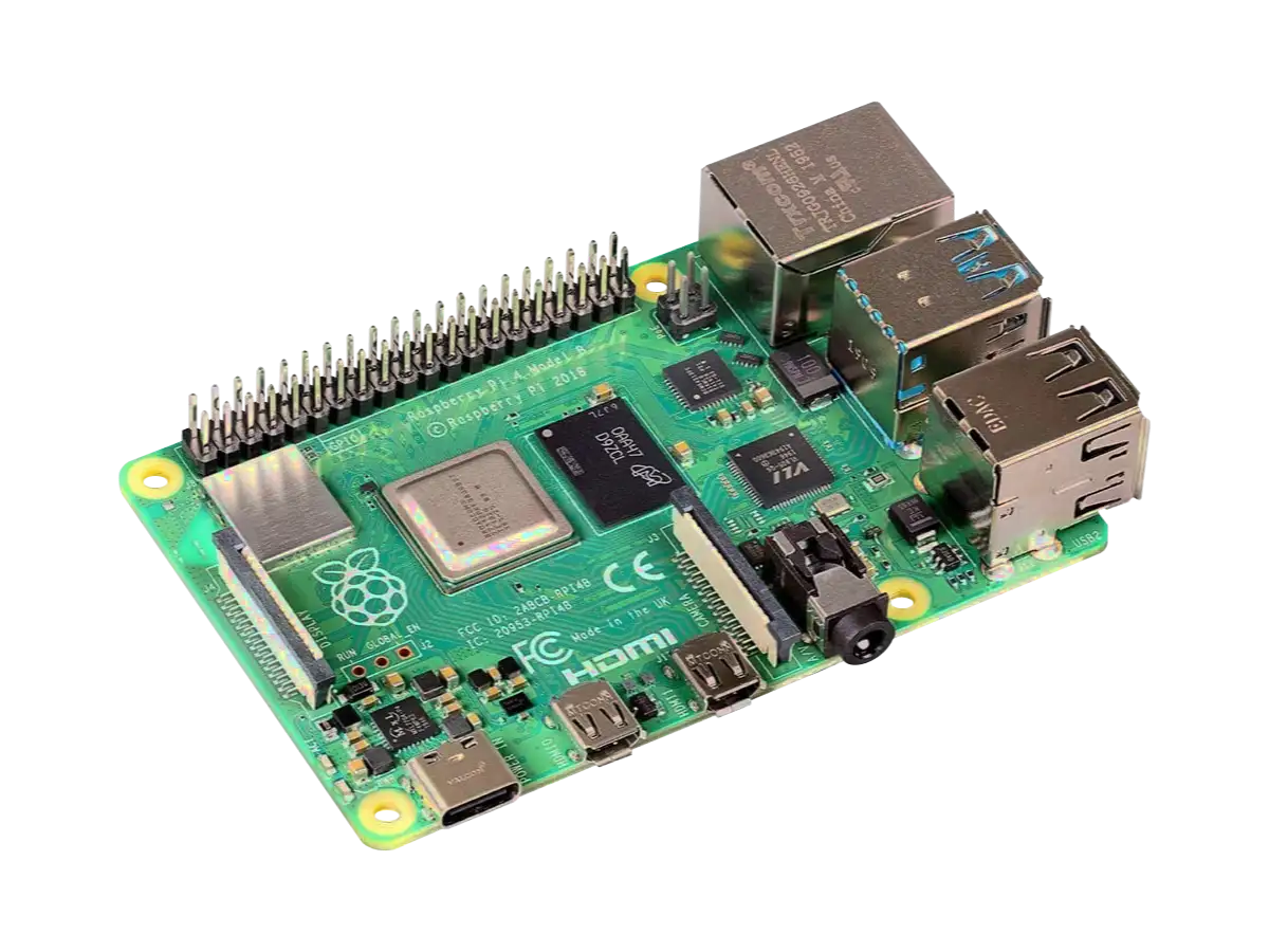
Raspberry Pi 4B (RPi4B) specs, board layout, components, I/O, and power.
Created:
02Aug2023 08:00:15 UTC
2023-08-02T08:00:15Z
Updated:
17Aug2024 08:45:11 UTC
2024-08-17T08:45:11Z
Rating: (0 reviewsThis article has not been rated yet)
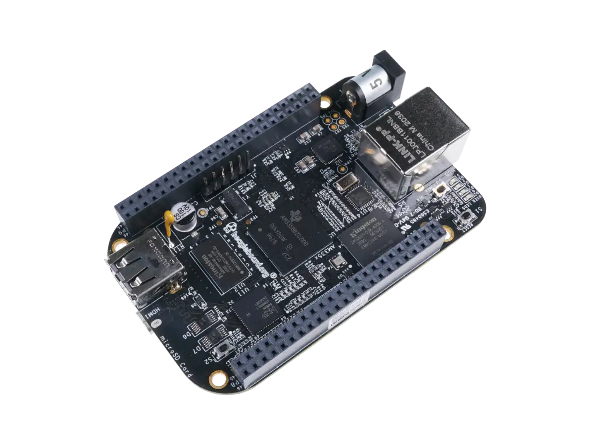
BeagleBone Black specs, board layout, components, I/O, and power.


(0) Comments
Sign in to leave a comment
Sign In