nRF24L01+ 2.4GHz Wireless Transceiver
Updated: 13Aug2024 05:10:34 UTC 2024-08-13T05:10:34Z
Rating: (0 reviewsThis article has not been rated yet)
The nRF24L01+ is a wireless RFRadio Frequency transceiver that provides 2-way half-duplex communications in the 2.4GHz ISMIndustrial, Scientific, and Medical radio bands band with a range up to a kilometer depending on the antenna used and environmental conditions. This frequency band is free to use in almost all countries for low power devices without a license. The specs and capabilities of the nRF24L01+, different breakout modules, and software libraries available will be covered.
nRF24L01+ IC
The nRF24L01+ ICIntegrated Circuit is a wireless transceiver chip by Nordic Semiconductor that provides 2-way half-duplex communications with GFSKGaussian Frequency-Shift Keying modulation modulation in the ISMIndustrial, Scientific, and Medical radio bands band between 2.400GHz to 2.525GHz with up to 126 channels. The nrf24L01+ has programmable RFRadio Frequency power output and air data rates with an SPISerial Peripheral Interface data interface (SCKSerial Clock line, MISOMaster In Slave Out (MISO) is the SPI data output line from the slave device, CEChip Enable (CE) is the SPI output line from the master device to enable the slave device., CSNChip Select (CSN) is the SPI output line from the master device to indicate that data is being sent. Also referred to as CS or SS (Slave Select).) that is 5V tolerant.
The "+" version is drop-in compatible with nRF24L01 and on-air compatible with nRF2401A, nRF2402, nRF24E1 and nRF24E2. Intermodulation and wideband blocking values in nRF24L01+ are much improved in comparison to the nRF24L01 and the addition of internal filtering to nRF24L01+ has improved the margins for meeting RFRadio Frequency regulatory standards.
IC Specs
| Parameter | Description |
|---|---|
| Manufacturer |
Nordic Semiconductor
(nRF24L01+ Datasheet PDF) |
| Frequency | 2.4GHz (2.400GHz to 2.525GHz) ISMIndustrial, Scientific, and Medical radio bands band |
| Modulation | GFSKGaussian Frequency-Shift Keying modulation |
| Channels |
Up to 126 channels
|
| Network | 6 data pipe MultiCeiver™ for 1:6 star networks |
| Air Data Rate (bpsbits per second) | Configurable: 250kbps, 1Mbps, and 2Mbps |
| Receiving Sensitivity (dBmDecibel-milliwatts (dBm) is a power level that expresses decibels in terms of milliwatts on a logarithmic scale.) |
|
| Transmitting Power (dBmDecibel-milliwatts (dBm) is a power level that expresses decibels in terms of milliwatts on a logarithmic scale.) |
Configurable:
|
| I/O Data Interface |
SPISerial Peripheral Interface (SCKSerial Clock line, MISOMaster In Slave Out (MISO) is the SPI data output line from the slave device, CEChip Enable (CE) is the SPI output line from the master device to enable the slave device., CSNChip Select (CSN) is the SPI output line from the master device to indicate that data is being sent. Also referred to as CS or SS (Slave Select).)
|
| Operating Supply Voltage | 1.9V to 3.9V DC |
| Power Consumption |
|
| Operating Temperature | -40°C to +85°C |
| Package | 20-pin 4x4mm QFNQuad Flat No-lead |
Air Data Rates
The air data rate is the modulated signaling rate the nRF24L01+ uses when transmitting and receiving data. It can be configured with a register to be 250kbpskilobits per second, 1MbpsMegabits per second, or 2MbpsMegabits per second. Using a lower air data rate gives better receiver sensitivity than higher air data rate, but a high air data rate gives lower average current consumption and reduced probability of on-air collisions.
Channels
The nRF24L01+ can operate on frequencies from 2.400GHz to 2.525GHz and transmits and receives data on a specific frequency known as a channel with up to 126 different channels available. In order for two nRF24L01+ modules to communicate with each other, they must be on the same channel. A channel occupies a bandwidth of less than 1MHz at 250kbps and 1Mbps and a bandwidth of less than 2MHz at 2Mbps.
The programming resolution of the RF channel frequency setting is 1MHz and at 2Mbps the channel occupies a 2MHz bandwidth, so to ensure non-overlapping channels in 2Mbps mode, the channel spacing must be set to 2MHz or more. The RF channel frequency is set by the RF_CH register according to the following formula:
Frequency [MHz] = 2400MHz + RF_CH [MHz]
For example, if you choose channel 50, the RF frequency will be 2400MHz + 50MHz = 2450MHz.
Each channel can have up to 6 addresses, where each unit can communicate with up to 6 other units at the same time.
MultiCeiver Network
The nRF24L01+ has a feature called MultiCeiver which stands for Multiple Transmitter Single Receiver. A MultiCeiver Network can contain a set of six parallel data pipes with unique addresses, where a data pipe is one of six logical channels within a single physical RFRadio Frequency channel.
Each data pipe has its own physical address (data pipe address) decoding in the nRF24L01+. As shown in the figure above, up to six nRF24L01+s configured as the primary transmitter (PTX) can communicate with one nRF24L01+ configured as a primary receiver (PRX). All data pipe addresses are searched for simultaneously and only one data pipe can receive a packet at a time.
Data Packets
The nRF24L01+ uses Enhanced ShockBurst™ for automatic packet handling and timing. When transmitting a packet, ShockBurst assembles the packet and clocks the bits in the data packet for transmission. When receiving a packet, ShockBurst constantly searches for a valid address in the demodulated signal and if a valid address is found it processes the rest of the packet and validates it by a CRCCyclic Redundancy Check. Each packet has five fields shown in the figure below.
- Preamble:
- Used to synchronize the receivers demodulator to the incoming bit stream. The preamble is one byte long and is either 01010101 or 10101010.
- Address:
- Ensures that the packet is detected and received by the correct receiver. You can configure the address field width to be 3, 4 or 5 bytes long. A valid packet is found by a matching address and a valid CRCCyclic Redundancy Check.
- Packet Control:
-
The 9 bit Packet Control field contains the following three subfields
-
Payload Length (6 bit):
Specifies the length of the payload in bytes. The length of the payload can be from 0 to 32 bytes. For example, 000000 = 0 byte is only used in empty ACKAcknowledgment packets and 100000 = 32 bytes. -
PID (2 bit):
Packet Identification used to detect if the received packet is new or retransmitted. This prevents the transmitting device from giving the same payload more than once to the receiving host MCUMicrocontroller Unit. -
NO_ACK (1 bit):
Flag used for the auto acknowledgment feature. When the flag is set high it tells the receiver that the packet is not to be auto acknowledged.
-
Payload Length (6 bit):
- Payload:
- The payload is the user defined message content of the packet. It can be 0 to 32 bytes long and either static or dynamic. The default is the static payload length, where all packets between the transmitter and receiver have the same length. Dynamic Payload Length (DPL) enables the transmitter to send packets with variable payload length to the receiver.
- CRCCyclic Redundancy Check:
- The CRCCyclic Redundancy Check is required for the error detection mechanism in the packet and no packet is accepted by Enhanced ShockBurst™ if the CRC fails. It is either 1 or 2 bytes and is calculated over the address, Packet Control Field, and Payload.
Automatic packet handing works as follows:
- The transmitter (PTX) sends a packet to the receiver (PRX) and waits short period set by the Auto Retransmit Delay (default 250µs) for the acknowledgment (ACK) to arrive.
- If the packet is received, the Enhanced ShockBurst automatically assembles and transmits an acknowledgment packet (ACK packet) to the PTX before returning to receive mode.
- If the PTX does not receive the ACKAcknowledgment packet within the Auto Retransmit Delay (ARD) time, Enhanced ShockBurst automatically retransmits the original data packet and sets the PTX in receive mode to wait for the ACK packet. This continues until acknowledgment is received or the maximum number of retransmits is reached (ARC).
You can configure the automatic packet handing parameters Auto Retransmit Delay (ARD) and the maximum number of retransmits (ARC).
nRF24L01+ Modules
nRF24L01+ Generic Module
The nRF24L01+ generic module is a radio transceiver designed to work in the 2.4GHz ISMIndustrial, Scientific, and Medical radio bands band from 2.400GHz to 2.525GHz with as many as 126 communication channels. The range of this module varies, with conflicting information on the internet, but is generally from 50 feet up to 200 feet in open air with a programmable RFRadio Frequency power output up to 0dBmDecibel-milliwatts (dBm) is a power level that expresses decibels in terms of milliwatts on a logarithmic scale. (1mW). Transmission communication is half-duplex with GFSKGaussian Frequency-Shift Keying modulation modulation and has selectable air data rates of 250kbpskilobits per second, 1MbpsMegabits per second, or 2MbpsMegabits per second.
The main difference between the NRF24L01 and NRF24L01+ versions of this module is the version without the + has only 1MbpsMegabits per second and 2MbpsMegabits per second baud rates, while the + version can also do 250kbpskilobits per second. The NRF24L01+ module has built-in hardware CRCCyclic Redundancy Check error detection and an auto-retransmit feature. Data interfacing and control is performed over SPISerial Peripheral Interface (SCKSerial Clock line, MISOMaster In Slave Out (MISO) is the SPI data output line from the slave device, CEChip Enable (CE) is the SPI output line from the master device to enable the slave device., CSNChip Select (CSN) is the SPI output line from the master device to indicate that data is being sent. Also referred to as CS or SS (Slave Select).) and is 5V tolerant. It has a power supply voltage ranging from 1.9V to 3.6V DC with 50mA nominal current, 250mA maximum current, and standby current of 22μA.
nRF24L01+ Mini Module
The nRF24L01+ 2.4GHz Mini module is a miniaturized SMDSurface Mount Device breakout of the nRF24L01+ with a size of 12mm x 18mm and pin spacing of 1.27mm (smaller than the standard generic nRF24L01+module that has a size of 15mm x 29mm with 2.54mm breadboard pin spacing). Other than the board size and pin spacing, the specs are the same as the standard generic module.
nRF24L01+PA+LNA Module
The nRF24L01+PAPower Amplifier+LNALow Noise Amplifier RFRadio Frequency Module is a long range 2.4GHz transceiver based on the nRF24L01+ chip, with an on board Power Amplifier (PAPower Amplifier) and Low Noise Amplifier (LNALow Noise Amplifier) included in an RFX2401C range extender chip. The PAPower Amplifier amplifies the signal that is being transmitted by the nRF24L01+ chip. The LNALow Noise Amplifier amplifies an extremely weak signal received from the antenna (usually below microvolts or -100dBmDecibel-milliwatts (dBm) is a power level that expresses decibels in terms of milliwatts on a logarithmic scale.) to a more useful level (usually around 0.5V to 1V). This amplification from an external antenna gives an increased range of up to 1100 meters.
nRF24L01+PA+LNA GT-24 Module
The GT-24 nRF24L01+PAPower Amplifier+LNALow Noise Amplifier RFRadio Frequency Module is a long range 2.4GHz transceiver based on the nRF24L01+ chip, with an on board Power Amplifier (PAPower Amplifier) and Low Noise Amplifier (LNALow Noise Amplifier) included in an RFX2401C range extender chip. The unique features of this board is that it has both a built-in PCBPrinted Circuit Board antenna and IPEX external antenna connector along with an 8-Pin interface that has 2.54mm pin spacing for breadboards and 1.27mm pin spacing on the end of the board.
nRF24L01+PA+LNA ML01DP5 Module
The nRF24L01+PAPower Amplifier+LNALow Noise Amplifier ML01DP5 RFRadio Frequency Module is is a long range 2.4GHz transceiver based on the nRF24L01+ chip, equipped with 20dBmDecibel-milliwatts (dBm) is a power level that expresses decibels in terms of milliwatts on a logarithmic scale. power amplifier chip which makes the transmitting power 100mW (20dBmDecibel-milliwatts (dBm) is a power level that expresses decibels in terms of milliwatts on a logarithmic scale.) and the receiving sensitivity -106dBmDecibel-milliwatts (dBm) is a power level that expresses decibels in terms of milliwatts on a logarithmic scale. (enhanced by 10dBDecibel (dB) used to express the ratio of two physical quantities such as power, sound intensity, sound pressure, voltage, and current on a logarithmic scale.) at 250kbpskilobits per second, giving a range up to 2300m. It has a power supply voltage ranging from 2.0V to 3.6V DC, with an emission current draw of 95mA and a receiving current of 20mA. The input data lines are 5V tolerant which allows for direct connection of SPISerial Peripheral Interface pins to 5V devices such as the Arduino.
nRF24L01+ Libraries
The nRF24L01+ modules have an SPISerial Peripheral Interface interface directly to the nRF24L01+ IC where specified register addresses need to be accessed in order to configure and pass data through the nRF24L01+. A library that handles the low level registry addressing and provides an interface with simple function calls with values and string command arguments would make these modules much easier to use. A few Arduino and MicroPython software libraries are mentioned below for the nRF24L01+ modules.
nRF24L01+ Arduino Libraries
There are many nRF24L01+ Arduino libraries available. The RF24 library is a core Arduino library that provides functions for sending and receiving messages. It is simple to use for beginners but offers advanced configuration options, and many examples are included to demonstrate various modes of communication. The library is compatible with all architectures and can be downloaded and installed into the Arduino IDE libraries folder. The Arduino RF24 library reference page has links to the code on GitHub and documentation.
RadioHead is another Arduino library written by Mike McCauley for the Airspayce company. This is an advanced library that supports many other radios, where there are different drivers for different RF modules (the driver for the nRF24L01+ is the RH_NRF24 driver with documentation). To install the RadioHead library on the Arduino IDEIntegrated Development Environment (IDE) is a software application that helps develop software code efficiently., first download the ZIP file from the Airspayce website, then launch the Arduino IDEIntegrated Development Environment (IDE) is a software application that helps develop software code efficiently., navigate to Sketch > Include Library > Add .ZIP Library, and choose the RadioHead file.
nRF24L01+ MicroPython Libraries
The nrf24l01.py driver is a core MicroPython library available on GitHub. Kevin McAleer has a YouTube video that shows how to use this driver with example code on GitHub.
Related Content

Created:
20Nov2023 02:03:58 UTC
2023-11-20T02:03:58Z
Updated:
13Aug2024 10:25:03 UTC
2024-08-13T10:25:03Z
Rating: (0 reviewsThis article has not been rated yet)
Overview of the nRF24L01+ wireless transceiver module covering specs, board layout, and pinout.
Created:
15Jun2023 18:15:24 UTC
2023-06-15T18:15:24Z
Updated:
15Aug2024 19:55:56 UTC
2024-08-15T19:55:56Z
Rating: (0 reviewsThis article has not been rated yet)
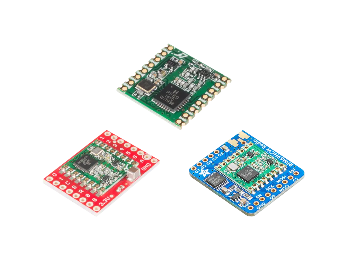
Comparison of different RFM69 RF Modules
- HopeRF Modules
- SparkFun Modules
- Adafruit Modules
Created:
19Jun2023 17:03:18 UTC
2023-06-19T17:03:18Z
Updated:
15Aug2024 20:00:13 UTC
2024-08-15T20:00:13Z
Rating: (0 reviewsThis article has not been rated yet)
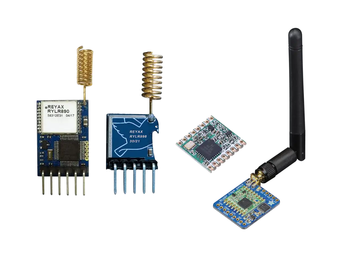
Comparison of different LoRa RF Modules
- Reyax Modules
- HopeRF Modules
- Adafruit Modules


(0) Comments
Sign in to leave a comment
Sign In