nRF24L01+ 2.4GHz Transceiver Module
Updated: 13Aug2024 10:25:03 UTC 2024-08-13T10:25:03Z
Rating: (0 reviewsThis article has not been rated yet)
The nRF24L01+ module is a radio transceiver designed to work in the 2.4GHz ISMIndustrial, Scientific, and Medical radio bands band from 2.400GHz to 2.525GHz with as many as 126 communication channels. The range of this module varies, with conflicting information on the internet, but is generally from 50 feet up to 200 feet in open air with a programmable RFRadio Frequency power output up to 0dBmDecibel-milliwatts (dBm) is a power level that expresses decibels in terms of milliwatts on a logarithmic scale. (1mW). Transmission communication is half-duplex with GFSKGaussian Frequency-Shift Keying modulation modulation and has selectable air data rates of 250kbpskilobits per second, 1MbpsMegabits per second, or 2MbpsMegabits per second.
The main difference between the NRF24L01 and NRF24L01+ versions of this module is the version without the + has only 1Mbps and 2Mbps baud rates, while the + version can also do 250Kbps. The NRF24L01+ module has built-in hardware CRCCyclic Redundancy Check error detection and an auto-retransmit feature. Data interfacing and control is performed over SPISerial Peripheral Interface (SCKSerial Clock line, MISOMaster In Slave Out (MISO) is the SPI data output line from the slave device, MOSIMaster Out Slave In (MOSI) is the SPI data output line from the master device, CEChip Enable (CE) is the SPI output line from the master device to enable the slave device., CSNChip Select (CSN) is the SPI output line from the master device to indicate that data is being sent. Also referred to as CS or SS (Slave Select).) and is 5V tolerant. It has a power supply voltage ranging from 1.9V to 3.6V DC with 11.3mA (max) transmitting current, 13.5mA (max) receiving current, and a minimum standby current of 26μA.
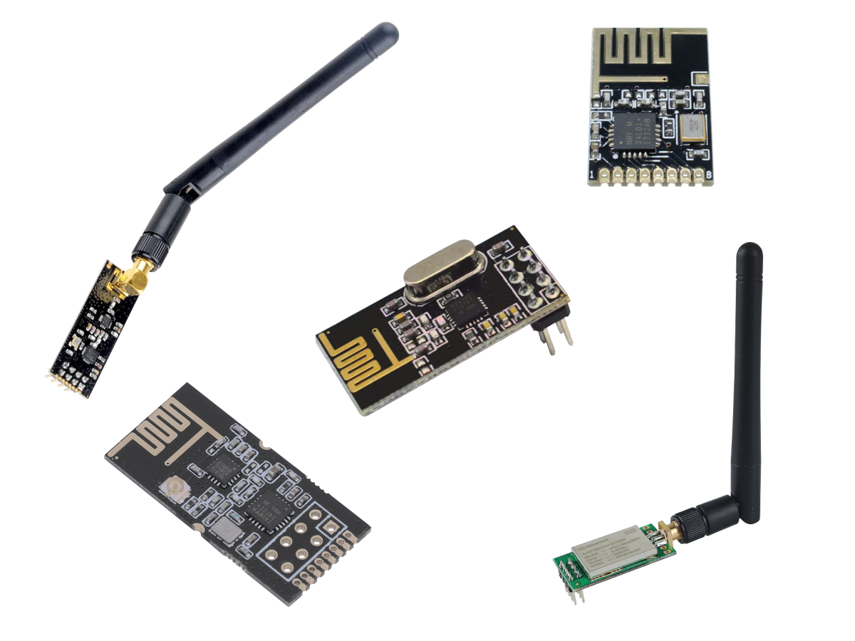
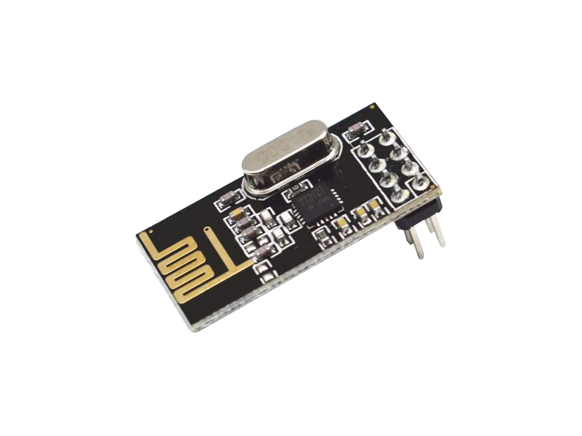
The contents of this article covers the nRF24L01+ module specifications, board layout with pinout, and accessories.
Specs
| Parameter | Description |
|---|---|
| Transceiver IC |
nRF24L01+ Single Chip 2.4GHz Transceiver
(nRF24L01+ Datasheet PDF) |
| Range | Generally from 50ft up to 200ft in open air |
| Frequency | 2.4GHz (2.400GHz to 2.525GHz) ISMIndustrial, Scientific, and Medical radio bands band |
| Modulation | GFSKGaussian Frequency-Shift Keying modulation |
| Channels |
Up to 126 Channels
|
| Air Data Rate (bpsbits per second) | Configurable: 250kbps, 1Mbps, and 2Mbps |
| Receiving Sensitivity (dBmDecibel-milliwatts (dBm) is a power level that expresses decibels in terms of milliwatts on a logarithmic scale.) |
Receiving Sensitivity depends on data rate:
|
| Transmitting Power (dBmDecibel-milliwatts (dBm) is a power level that expresses decibels in terms of milliwatts on a logarithmic scale.) |
Configurable:
|
| Antenna | Built in PCBPrinted Circuit Board MIFAMeandered Inverted-F Antenna |
| I/O Data Interface |
Pin Through Holes with 2.54mm (0.1in) spacing
|
| Operating Supply Voltage | 3.2V to 5.5V DC |
| Power Consumption |
|
| Operating Temperature | -40°C to +85°C |
| Board Size (LxW) | 28.5mm x 15.2mm (1.12in x 0.60in) |
Board Layout
| Pin | Function |
|---|---|
| VCC | Operating voltage 1.9V to 3.9V DC. |
| GND | Common ground with a white square marking to distinguish it from other pins. |
| CSN | Chip Select Not is an active LOW pin when communicating with the nRF24L01+ over SPI. Set to HIGH when not communicating with the nRF24L01+. |
| CE | Chip Enabled is an active HIGH pin used to select the mode of the nRF24L01+. |
| MOSI | Master Out, Slave In pin where the master device sends data to the slave (nRF24L01+). |
| MISO | Master In, Slave Out pin where the slave (nRF24L01+) sends data to the master device. |
| SCK | Serial clock pulses from the master device used for SPI. |
| IRQ | Interrupt Request pin that alerts the master device when new data is available to process. |
Even though VCC has a voltage range of 1.9V to 3.9V DC, the logic pins CE, CSN, MOSI, MISO, SCK and IRQ are 5V tolerant.
Accessories
Breadboard Adapters
The parallel layout of the 2x4 pin header on the NRF24L01+ module unfortunately is not breadboard friendly. You can use an adapter shown below that separates each 4 pin row to connect this module to a breadboard.
Regulator Adapters
The nRF24L01+ module has a power supply voltage ranging from 1.9V to 3.6V DC, so if you want to power this module with a 5V microcontroller that does not have a 3.3V output, the supply voltage must be reduced with a step-down converter.
There are 3.3V regulator adapters designed for the NRF24L01+ module shown in the figure below. These adapters can also be useful if your power supply is noisy. A circuit that generates a radio frequency (RF) signal is extremely sensitive to power supply noise, which can significantly reduce the range you can achieve. The nRF24L01+ adapters contain both a regulator and filter capacitor to reduce the noise and increase the range of your nRF24L01+ module.

(0) Comments
Sign in to leave a comment
Sign In