RFM69 Wireless Transceiver Modules
Updated: 15Aug2024 19:55:56 UTC 2024-08-15T19:55:56Z
Rating: (0 reviewsThis article has not been rated yet)
The HopeRF RFM69 RFRadio Frequency transceiver boards are based on the Semtech SX1231H ICIntegrated Circuit that are designed to work in the ISMIndustrial, Scientific, and Medical radio bands and SRDShort Range Device frequency bands of 315MHz, 433MHz, 868MHz, and 915MHz. They have a range up to 500 meters line-of-sight using simple wire antennas, where higher ranges can be achieved by using a better antenna or by lowering the data bit rate.
The RFM69 communication is half-duplex and supports transmission modulations FSKFrequency-Shift Keying modulation, GFSKGaussian Frequency-Shift Keying modulation, MSKMinimum-Shift Keying modulation, GMSKGaussian Minimum-Shift Keying modulation, and OOKOn-Off Keying modulation. The maximum air data rate is 300kbpskilobits per second using FSKFrequency-Shift Keying modulation. They can operate in either a continuous transmit mode or packet mode. The packet mode has the benefit of error correction and can also auto-retransmit. The data interface uses a 4-wire SPISerial Peripheral Interface as well as interrupt and reset trigger digital inputs.
The HopeRF RFM69 transceivers are available as stand-alone modules or embedded in a breakout board such as the SparkFun and Adafruit RFM69HCW modules. The breakout boards widen the 2.0mm pin spacing on the HopeRF RFM69 board to 2.54mm (0.1in) breadboard pin spacing, have bypass capacitors to reduce noise from the power supply, and the Adafruit's breakout boards come with 5V to 3.3V level shifting for both power and data to make them compatible with 5V microcontrollers.
HopeRF Modules
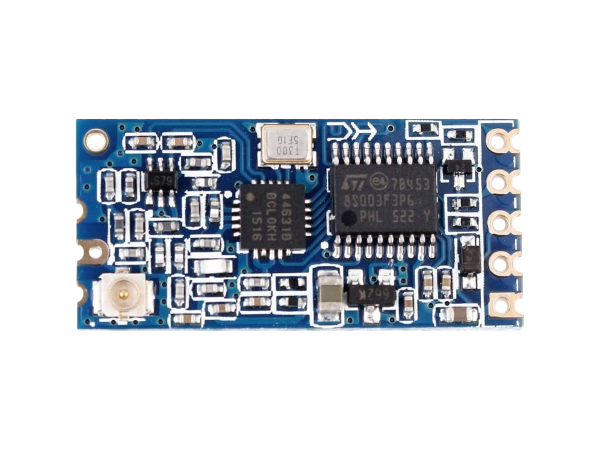
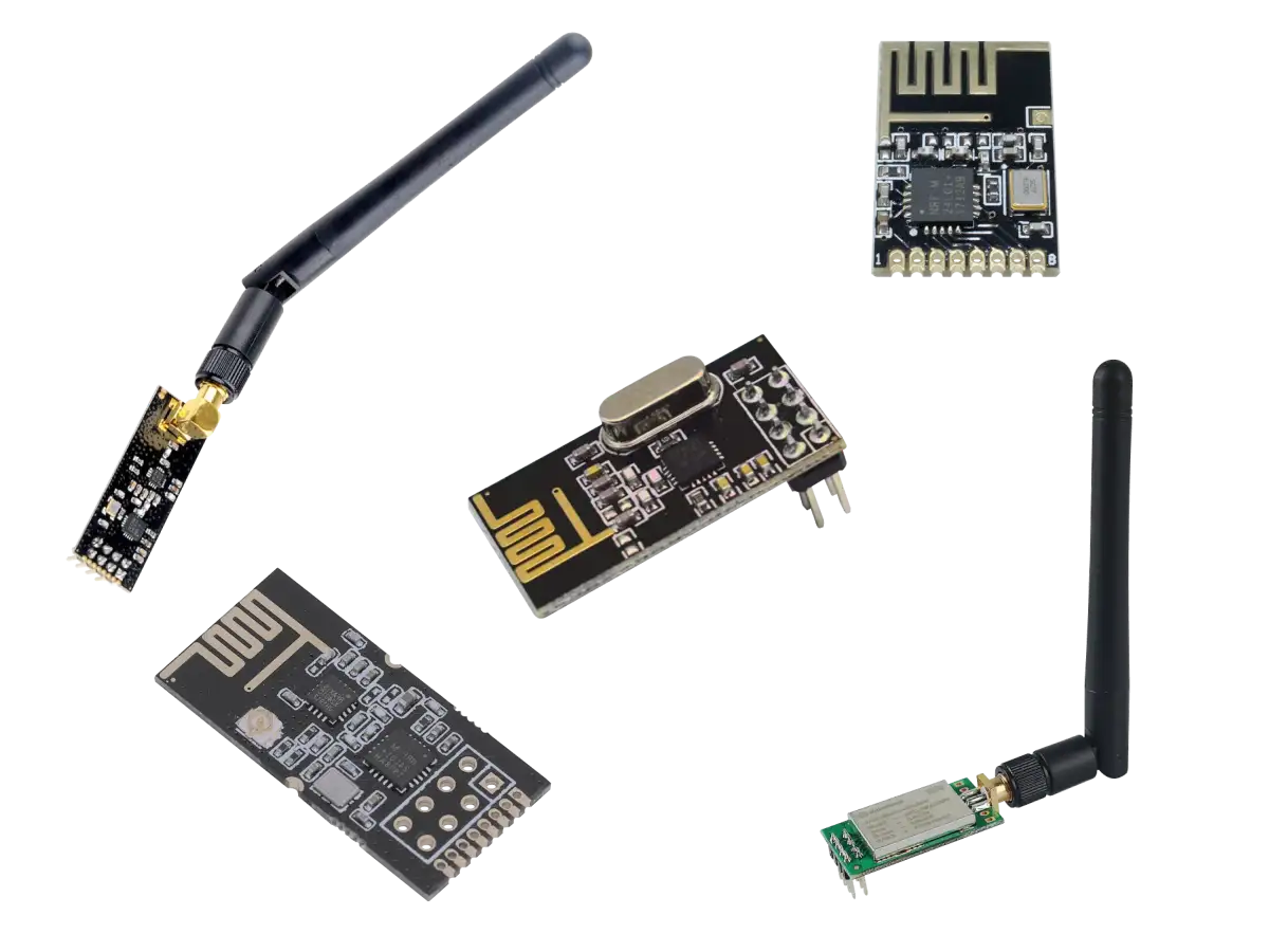
There are four different versions of the HopeRF RFM69.
- RFM69W
- RFM69CW
- RFM69HW
- RFM69HCW
These four versions are shown in the figures below.
The "H" in the names RFM69HW and RFM69HCW stands for "high power" version with a +20dBmDecibel-milliwatts (dBm) is a power level that expresses decibels in terms of milliwatts on a logarithmic scale. maximum output compared to the RFM69W and RFM69CW with +13dBmDecibel-milliwatts (dBm) is a power level that expresses decibels in terms of milliwatts on a logarithmic scale. maximum output.
The "C" in the names stands for "compatible" in size and pinout with an older radio that it was upgraded from. The RFM69CW was intended as an upgrade path for the RFM12B and the RFM69HCW was an upgrade path for the RFM22B, so these boards have the same size and pinout.
The size and pinout of the RFM69W (16mm x 19.7mm) and RFM69CW (16mm x 16mm) are different, but otherwise the boards are functionally equivalent. Likewise with the high power boards, where the size and pinout of the RFM69HW (16mm x 19.7mm) and RFM69HCW (16mm x 16mm) are different, but otherwise the boards are functionally equivalent.
| Parameter | Description |
|---|---|
| Modules | RFM69W RFM69CW RFM69HW RFM69HCW |
| Main IC | SX1231H by Semtech |
| Frequencies |
ISMIndustrial, Scientific, and Medical radio bands bands
|
| Modulation | FSKFrequency-Shift Keying modulation, GFSKGaussian Frequency-Shift Keying modulation, MSKMinimum-Shift Keying modulation, GMSKGaussian Minimum-Shift Keying modulation, and OOKOn-Off Keying modulation |
| Air Data Rate (bpsbits per second) | Configurable with FSKFrequency-Shift Keying modulation Bit rates up to 300kbps |
| Receiving Sensitivity (dBmDecibel-milliwatts (dBm) is a power level that expresses decibels in terms of milliwatts on a logarithmic scale.) | Down to -120dBm at 1.2kbps |
| Transmitting Power (dBmDecibel-milliwatts (dBm) is a power level that expresses decibels in terms of milliwatts on a logarithmic scale.) |
Programmable with 1dB steps
|
| I/O Data Interface |
I/O Data Pins are 3.3V
|
| Data Packets |
|
| Operating Supply Voltage |
RFM69HCW & RFM69HW:
|
| Transmission Current |
|
| Receiving Current | 16mA |
| Sleep Current | 0.1μA (typical), 1μA (max) |
| Idle Current | 1.2μA (typical) |
| Synthesizer Current | 9mA (typical) |
| Networking |
Supports multipoint networks with individual node addresses
|
| Board Size |
|
SparkFun Modules
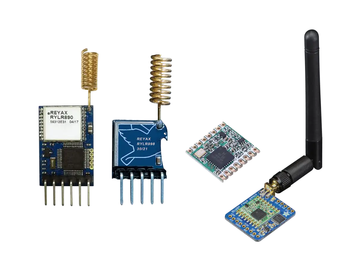
The SparkFun RFM69HCW modules breaks out all the pins for the RFM69HCW and widens the 2.0mm pin spacing RFM69HCW to 2.54mm (0.1in) breadboard spacing. SparkFun has two RFM69HCW versions with different radio frequencies shown in the figures below: the 434MHz version (WRL-12823) and 915MHz version (WRL-12775).
Although the SparkFun board includes the 915MHz RFM69HCW version, it can also be used at 868MHz when changing the software configuration to this frequency. There is only minor passive component differences between the two versions of the 868MHz and 915MHz RFM69HCW and open air testing reveals no significant signal strength difference using the 915MHz RFM69HCW with 868MHz settings.
This board also features pin through holes to solder a simple wire antenna or a PCBPrinted Circuit Board to SMASubMiniature version A (SMA) connector cable for an SMASubMiniature version A (SMA) connector antenna. The range of these modules can go up to 500 meters line-of-sight using simple wire antennas, where higher ranges can be achieved by using a better antenna or by lowering the data bit rate.
| Parameter | Description |
|---|---|
| Modules | |
| RFM69 | RFM69HCW 433MHz & 915MHz based on the SX1231H IC |
| Frequency |
ISMIndustrial, Scientific, and Medical radio bands bands
|
| Modulation | FSKFrequency-Shift Keying modulation, GFSKGaussian Frequency-Shift Keying modulation, MSKMinimum-Shift Keying modulation, GMSKGaussian Minimum-Shift Keying modulation, and OOKOn-Off Keying modulation |
| Air Data Rate (bpsbits per second) | Configurable with FSKFrequency-Shift Keying modulation Bit rates up to 300kbps |
| Receiving Sensitivity (dBmDecibel-milliwatts (dBm) is a power level that expresses decibels in terms of milliwatts on a logarithmic scale.) | Down to -120dBm at 1.2kbps |
| Transmitting Power (dBmDecibel-milliwatts (dBm) is a power level that expresses decibels in terms of milliwatts on a logarithmic scale.) |
|
| I/O Data Interface |
I/O Data Pins are 3.3V
|
Data Packets |
|
| Operating Supply Voltage |
|
| Transmission Current |
|
| Receiving Current | 16mA |
| Networking |
Supports multipoint networks with individual node addresses.
|
| Board Size (LxW) | 20.32mm x 27.94mm (0.8in x 1.1in) |
Adafruit Modules
The Adafruit RFM69HCW modules breaks out all the pins for the RFM69HCW and widens the 2.0mm pin spacing to 2.54mm (0.1in) breadboard spacing. Adafruit has two RFM69HCW versions with different radio frequencies shown in the figures below: the 434MHz version (PID 3071) and 868MHz/915MHz version (PID 3070).
The Adafruit 868MHz/915MHz board includes the 915MHz HCW69HCW module, but it can also be used at 868MHz when changing the software configuration to this frequency. There is only minor passive component differences between the two versions of the 868MHz and 915MHz RFM69HCW and open air testing reveals no significant signal strength difference using the 915MHz RFM69HCW with 868MHz settings.
This board also features a PCBPrinted Circuit Board spot with the option to solder on a uFL or SMASubMiniature version A (SMA) connector antenna connector or a simple wire antenna. The range of these modules can go up to 500 meters line-of-sight using simple wire antennas, where higher ranges can be achieved by using a better antenna or by lowering the data bit rate.
| Parameter | Description |
|---|---|
| Modules | |
| RFM69 | RFM69HCW 433MHz & 915MHz based on the SX1231H IC |
| Frequency |
ISMIndustrial, Scientific, and Medical radio bands band
|
| Modulation | FSKFrequency-Shift Keying modulation, GFSKGaussian Frequency-Shift Keying modulation, MSKMinimum-Shift Keying modulation, GMSKGaussian Minimum-Shift Keying modulation, and OOKOn-Off Keying modulation |
| Air Data Rate (bpsbits per second) | Configurable with FSKFrequency-Shift Keying modulation Bit rates up to 300kbps |
| Receiving Sensitivity (dBmDecibel-milliwatts (dBm) is a power level that expresses decibels in terms of milliwatts on a logarithmic scale.) | Down to -120dBm at 1.2kbps |
| Transmitting Power (dBmDecibel-milliwatts (dBm) is a power level that expresses decibels in terms of milliwatts on a logarithmic scale.) |
|
| I/O Data Interface |
|
| Data Level Shifter IC | TITexas Instruments 74HC4050D High-Speed CMOS Logic Hex Buffer (74HC4050D Datasheet PDF) |
| Data Packets |
|
| Operating Supply Voltage | 3.3V to 6V DC |
| Supply Voltage Regulator IC |
|
| Transmission Current | 50mA (+13dBm) to 150mA (+20dBm) |
| Receiving Current | 30mA |
| Networking |
Supports multipoint networks with individual node addresses
|
| Board Size (LxWxH) | 25.3mm x 29.3mm x 3.5mm (1.0in x 1.15in x 0.14in) |
RFM69 Libraries
Arduino
There are many RFM69 Arduino libraries available, such as as the LowPowerLab's RFM69 Library and AirSpayce's Radiohead Library which also supports many other radios.
CircuitPython
The Adafruit CircuitPython RFM69 Library is available on GitHub that can be used with either Adafruit's RFM69 boards or other RFM69 modules. There is also a usage guide for this library available on Adafruit's website and documentation. CircuitPython was designed to be beginner friendly but has some limitations, where interrupts and threading are not supported, so if these features are needed you can use the MicroPython library given below.
MicroPython
A MicroPython Library by MCHobby is available on GitHub that is based on the Arkorobotics RFM MicroPython Library for the Pyboard, Adafruit's CircuitPython, and the LowPowerLabs Arduino Library. MC Hobby also has a Wiki page that describes the hardware and communication with an example that uses the Adafruit RFM69 board with a Raspberry Pi Pico microcontroller.


(0) Comments
Sign in to leave a comment
Sign In