IoT WiFi Modules
Updated: 15Aug2024 23:21:16 UTC 2024-08-15T23:21:16Z
Rating: (0 reviewsThis article has not been rated yet)
A WiFi module is a self-contained unit that consists of a processor chip (MCUMicrocontroller Unit or SoCSystem On a Chip), along with other components needed by the processor chip in order for it to function, such as an external flash memory chip, voltage regulator, oscillator, and PCBPrinted Circuit Board antenna or uFL connector for an external antenna.
WiFi modules have VCCVoltage Collector Collector (VCC) is the supply voltage at the collector of a transistor. The double subscript notation of repeating letters "CC" is used to denote a power supply voltage that is relative to ground. and GNDCommon Ground pins that are used to provide power to the module components and I/OInput/Output pins for interfacing the processor. Some modules have their circuitry open (e.g., ESP-01), but most are shielded with a tin cover that acts as a Faraday cage to reduce EMIElectromagnetic Interference.
This overview covers the most common WiFi modules used in IoTInternet Of Things applications, such as the ESP8266, ESP32, and the ATWINC1500.
ESP8266
The defining feature of ESP8266 modules is the ESP8266EX SoCSystem On a Chip chip by Espressif. The ESP8266EX SoC integrates a Tensilica based L106 single core 32-bit MCUMicrocontroller Unit that runs at 80MHz (default) or 160MHz, antenna transmit-receive switches, RF balun, PAPower Amplifier, LNALow Noise Amplifier, filters, and power management.
The ESP8266EX SoC supports 2.4GHz 802.11IEEE 802.11 is a set of protocol standards that define communication for a Wireless Local Area Network (WLAN). In order for WiFi to work between different devices, they all need to agree on how they are going to communicate. The current version of the standard is IEEE 802.11-2007, with many amendments such as 802.11a, 802.11b, 802.11g, and 802.11n.b/g/n WiFi up to 72.2Mbps, three WiFi modes (APA WiFi Access Point (AP) is a device that creates a wireless local area network, or WLAN, and acts as a central hub that allows other devices, such as smartphones or computers, to connect to it over WiFi., STAA WiFi Station (STA) is a device that has the capability to connect to an existing WiFi network as a client in the same way other devices, such as smartphones or computers, join an established network and communicate with other devices on that network or access the internet., AP+STAA WiFi device in AP+STA mode acts as both an Access Point (AP) as well as a Station (STA), where the device can connect to an existing network as a client (STA) while simultaneously hosting its own network (AP) for other devices to connect to.), with UARTUniversal Asynchronous Receiver-Transmitter/I2CInter-Integrated Circuit. Also referred to as IIC or I2C./SPISerial Peripheral Interface/SDIOSecure Digital Input Output (SDIO) is a communication interface that allows devices to connect to an SD card and exchange data./I2SInter-IC Sound communication interfaces, and GPIOGeneral Purpose Input Output/PWMPulse-Width Modulation/ADCAnalog-to-Digital Converter (ADC, A/D, or A-to-D) peripheral interfaces. There is no programmable ROMRead-Only Memory in the ESP8266EX SoC, so the user program must be stored in an external SPI flash chip on the module. More details on the ESP8266EX chip can be found in the ESP8266EX Datasheet (PDF).
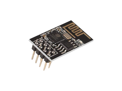
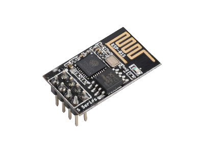
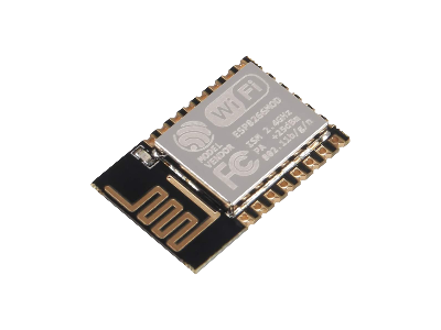
The ESP-01 and ESP-12 are two most common modules based on the ESP8266EX chip. The main difference between these two modules are their form factor and number of I/O pins the modules make available. The ESP-01 is a smaller module with a UART (RXReceive, TXTransmit) interface and only two GPIO pins. The ESP-12 offers more I/O pins, including I2C/SPI/SDIO interfaces, GPIO pins, and a 10-bit ADC pin, that offers more flexibility for connecting sensors and other peripherals.
ESP8266 ESP-01 & ESP-01S
The ESP8266 ESP-01 is an inexpensive 802.11IEEE 802.11 is a set of protocol standards that define communication for a Wireless Local Area Network (WLAN). In order for WiFi to work between different devices, they all need to agree on how they are going to communicate. The current version of the standard is IEEE 802.11-2007, with many amendments such as 802.11a, 802.11b, 802.11g, and 802.11n.b/g/n 2.4GHz WiFi module with an integrated TCP/IPTCP/IP is a suite of internet communication protocols. TCP (Transmission Control Protocol) is responsible for establishing reliable, ordered data delivery, and handling congestion control, while IP (Internet Protocol) focuses on routing packets of data to their destination. protocol stack that can give a microcontroller access to your WiFi network. The ESP-01 module contains an ESP8266EX SoCSystem On a Chip, 512kB flash memory chip, RFRadio Frequency circuitry, and built in PCBPrinted Circuit Board trace antenna (MIFAMeandered Inverted-F Antenna) on a miniature development board the size of 24.8mm x 14.3mm (0.98in x 0.56in). The board also has two LEDLight Emitting Diodes: a red one that indicates power and a blue one that indicates data flow and can also be controlled by programming.
The ESP-01 can be programmed through its (RXReceive, TXTransmit) pins using a USB Serial Adapter (USB-to-TTL converter), a microcontroller with USB serial, or a dedicated ESP-01 USB Programmer. The firmware can be LuaLua (meaning moon) is a lightweight, high-level, multi-paradigm, open source programming language built on top of the C programming language and designed primarily for embedded use in applications. code, Arduino code, MicroPython code, or programmed directly through ATShort text string commands where the AT stands for ATtention and every command line starts with "AT" or "at". commands. The ESP-01 module has three WiFi modes it can operate in: APA WiFi Access Point (AP) is a device that creates a wireless local area network, or WLAN, and acts as a central hub that allows other devices, such as smartphones or computers, to connect to it over WiFi., STAA WiFi Station (STA) is a device that has the capability to connect to an existing WiFi network as a client in the same way other devices, such as smartphones or computers, join an established network and communicate with other devices on that network or access the internet., AP+STAA WiFi device in AP+STA mode acts as both an Access Point (AP) as well as a Station (STA), where the device can connect to an existing network as a client (STA) while simultaneously hosting its own network (AP) for other devices to connect to..
The board operates on 3.3V power and logic, so a voltage converter will be necessary when connecting to 5V devices. The power consumption is about 100mA on average for continuous transmission, but can spike up to 300mA. There are low power modes for battery operation, such as modem sleep (20mA), light sleep (2mA), and deep sleep (0.02mA).
The ESP-01S was intended as an upgrade to the ESP-01 with the following changes:
- ESP-01S has an antenna redesign providing slightly better signal strength and range
- ESP-01 has 512kB flash memory and ESP-01S has 1MB flash memory
- ESP-01 has two LEDLight Emitting Diodes: a red power indicator and blue serial transmitter indicator. The ESP-01S has only one blue LEDLight Emitting Diode that flashes temporarily when power is applied and flashes when there is serial activity.
- There are 3 new on-board pull-up resistors on the ESP-01S module that provide a logic HIGH to pins RST, GPIO0, and CH_PD.
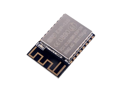
ESP8266 ESP-12
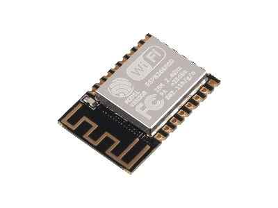
The ESP8266 ESP-12E/F/S modules by AI-Thinker consists of an ESP8266EX MCU core, built-in PCB antenna, and 2mm spaced pins on the edge of the board for power and I/O. These modules have UART/I2C/SPI/SDIO communication interfaces, GPIO pins, and a 10-bit ADC pin. The module supports 2.4GHz 802.11b/g/n WiFi up to 72.2Mbps, with three WiFi modes it can operate in (APA WiFi Access Point (AP) is a device that creates a wireless local area network, or WLAN, and acts as a central hub that allows other devices, such as smartphones or computers, to connect to it over WiFi., STAA WiFi Station (STA) is a device that has the capability to connect to an existing WiFi network as a client in the same way other devices, such as smartphones or computers, join an established network and communicate with other devices on that network or access the internet., AP+STAA WiFi device in AP+STA mode acts as both an Access Point (AP) as well as a Station (STA), where the device can connect to an existing network as a client (STA) while simultaneously hosting its own network (AP) for other devices to connect to.).
The original ESP-12 module is outdated and replaced by its successors: the EPS-12E, ESP-12F, and ESP-12S. All three versions have the same functionality and are all compatible with the same form factor (24mm x 16mm), 2mm pin spacing, and built-in PCB antenna. The ESP-12E version is shown below.
The ESP-12F has an improved circuit and antenna design for better radio performance over the ESP-12E. The ESP-12F is the same size and fully compatible with the previous version ESP-12E.
The ESP-12S has an improved PCB layout and antenna design for better radio performance over the ESP-12F. The ESP-12S is the same size and fully compatible with previous versions ESP-12F and ESP-12E. However, the pin count has been reduced from 22 to 16, with pins on the bottom of the board removed (the SPI pins can be accessed with multi-functional GPIO pins on the side of the board). The breakout pads of the ESP-12S module are also smaller with no more pin through holes, just castellations.
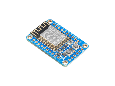
ESP8266 Adafruit Huzzah
The Adafruit HUZZAH ESP8266 Breakout board (PID 2471) has an ESP-12F module broken out into 0.1" headers, with a 3.3V 500mA onboard regulator that allows a supply voltage from 3.4V to 6V DC, two onboard buttons (a reset button and bootload button), and a red LED you can control. The ESP-12F module contains an ESP8266EX SoC, 4MB flash memory chip, and built-in PCB antenna (MIFAMeandered Inverted-F Antenna).
The HUZZAH board breaks out the ESP8266EX I/O (3.3 max) into 9x GPIO (which can also be used for I2C or SPI), 2x UART, and 1x analog input (10-bit ADC, 1.0V max). Control inputs include reset, enable, and LDOLow Dropout Regulator-disable pins. The size of the HUZZAH board is 38mm x 25mm (1.50in x 0.98in).
ESP32
The ESP32 series chips are an upgrade to the ESP8266 designed for a wide range of applications, from low power IoTInternet Of Things sensors to more demanding task such as voice encoding, music streaming, and MP3Moving Picture Experts Group Layer-3 Audio (MP3) is a coding format for digital audio that uses lossy compression to reduce the overall file size.MP3 files are audio files used for storing and transferring music on computers, smartphones, online, and portable MP3 players. decoding.
The ESP32 has several advantages over the ESP8266 with more processing power, higher memory capacity, faster WiFi with stronger security features, Bluetooth v4.2 BRBasic Rate/EDREnhanced Data Rate and BLEBluetooth Low Energy, more GPIOGeneral Purpose Input Output pins, a higher resolution 12-bit ADCAnalog-to-Digital Converter (ADC, A/D, or A-to-D) with more channels, two 8-bit DACDigital-to-Analog Converter (DAC, D/A, or D-to-A)s, and more communication interfaces. More details on the ESP32 chips can be found in the ESP32 Series Datasheet (PDF).
| Feature | ESP8266EX | ESP32 |
|---|---|---|
| Processor |
Xtensa 32-Bit L106
|
Xtensa 32-Bit LX6
|
| WiFi |
|
|
| Bluetooth | None | BTBluetooth v4.2 BRBasic Rate/EDREnhanced Data Rate and BLEBluetooth Low Energy |
| Communication |
|
|
| GPIOGeneral Purpose Input Output | 17 pins | 34 pins |
| PWMPulse-Width Modulation | 8 Channels | 16 Channels |
| ADCAnalog-to-Digital Converter (ADC, A/D, or A-to-D) | 10-Bit, 1 Channel | 12-Bit, 18 Channels |
| DACDigital-to-Analog Converter (DAC, D/A, or D-to-A) | None | 2x 8-Bit DACs |
There are several different kinds of ESP32 modules with different chips (including ESP32-D0WD, ESP32-D0WDQ6, ESP32-D2WD, and ESP32-S0WD). The table below provides which chips are inside some common modules. A more comprehensive list of ESP32 modules and chips can be found on Wikipedia.
| Module | Chip | Description | Datasheet |
|---|---|---|---|
|
Espressif ESP32-WROOM-32 |
ESP32-D0WDQ6
|
|
ESP32-WROOM-32 Datasheet
(PDF) |
|
Espressif ESP32-WROOM-32D |
ESP32-D0WD
|
Revision of the ESP-WROOM-32 module which uses an
ESP32-D0WD chip instead of an ESP32-D0WDQ6 chip.
|
ESP32-WROOM-32D Datasheet
(PDF) |
|
Espressif ESP32-WROOM-32U |
ESP32-D0WD
|
Alternative to the ESP-WROOM-32D module that has a uFL connector for an external
antenna.
|
ESP32-WROOM-32U Datasheet
(PDF) |
|
Espressif ESP32-WROOM-32E |
ESP32-D0WD-V3 or ESP32-D0WDR2-V3
|
Upgrade to the ESP32-WROOM-32D that fixes some bugs with a new chip version.
|
ESP32-WROOM-32E Datasheet
(PDF) |
|
Espressif ESP32-WROOM-32UE |
ESP32-D0WD-V3 or ESP32-D0WDR2-V3
|
Alternative to the ESP-WROOM-32E module that has a uFL connector for an external
antenna.
|
ESP32-WROOM-32UE Datasheet
(PDF) |
|
u-blox NINA-W102 |
ESP32-D0WDQ6-V3
|
|
u-blox NINA-W102 Datasheet
(PDF) |
|
Espressif ESP32-Mini-1 |
ESP32-U4WDH
|
|
ESP32-Mini-1 Datasheet
(PDF) |
ESP32-WROOM-32
The Espressif ESP32-WROOM-32 module combines 2.4GHz WiFi (802.11b/g/n) and Bluetooth (BT v4.2 BRBasic Rate/EDREnhanced Data Rate and BLEBluetooth Low Energy) for a wide range of applications, from low power IoT sensors to more demanding task such as voice encoding, music streaming and MP3Moving Picture Experts Group Layer-3 Audio (MP3) is a coding format for digital audio that uses lossy compression to reduce the overall file size.MP3 files are audio files used for storing and transferring music on computers, smartphones, online, and portable MP3 players. decoding.
The ESP32-WROOM-32 module contains an ESP32-D0WDQ6 SoC, 4MB/8MB/16MB SPI Flash memory chip, 40MHz Crystal Oscillator, PCB Antenna, and some discrete passive components, all on the same board with a size of 25.5mm x 18mm. The module has supply voltage range is between 3.0V and 3.6V and the max I/O logic voltage level is 3.3V.
The ESP32-D0WDQ6 SoC by Espressif is part of the ESP32 series chips that integrates an Xtensa 32-bit LX6 Dual-Core MCUMicrocontroller Unit with a clock frequency up to 240MHz, RF circuitry for WiFi and Bluetooth, cryptographic hardware acceleration, RTCReal-Time Clock, and power management. Communication interfaces include UARTUniversal Asynchronous Receiver-Transmitter, I2CInter-Integrated Circuit. Also referred to as IIC or I2C., SPISerial Peripheral Interface, I2SInter-IC Sound, SDIOSecure Digital Input Output (SDIO) is a communication interface that allows devices to connect to an SD card and exchange data., CANController Area Network (CAN) is a high-integrity serial communication bus designed for harsh environments such as industrial and automotive applications., RMTRemote Control Transceiver (RMT) is a peripheral in ESP32 chips that was designed to act as an infrared transceiver that can generate precise timing pulses on a GPIO pin. Due to the flexibility of its data format, RMT can be extended to a versatile and general-purpose transceiver, transmitting or receiving many other types of signals., and ETHEthernet (Ethernet requires external physical interface device to connect to physical LANLocal Area Network bus). Peripheral interfaces include GPIOGeneral Purpose Input Output, PWMPulse-Width Modulation, Capacitive Touch inputs, 12-bit ADCAnalog-to-Digital Converter (ADC, A/D, or A-to-D), and 8-bit DACDigital-to-Analog Converter (DAC, D/A, or D-to-A).
The ESP32-WROOM-32 module has a total of 38 contellated pins running along the edges of the board (14 pins on each of the long side edges and 10 pins on bottom short edge) to interface to the ESP32-D0WDQ6 SoC and SPI flash chip. More details on this module can be found in the ESP32-WROOM-32 Datasheet (PDF).
This module was originally named "ESP-WROOM-32", so you may see some older modules on the market with this label. Some vendors list the module with a "-N4", "-N8", or "-N16" at the end of the name to indicate the memory capacity (in MB) of the SPI Flash chip inside the module. For example, the ESP32-WROOM-32-N4 has 4MB, ESP32-WROOM-32-N8 has 8MB, and ESP32-WROOM-32-N16 has 16MB of SPI flash memory.
The inside of a ESP32-WROOM-32 module with the tin cover removed is shown below (from Wikipedia).
The ESP32-WROOM-32D is a revision of the ESP-WROOM-32 module which uses a ESP32-D0WD chip with a smaller footprint instead of an ESP32-D0WDQ6 chip. The ESP32-WROOM-32D module has the same functionality as the ESP32-WROOM-32, with both having the same size and are pin compatible.
The ESP32-WROOM-32U module is an alternative to the ESP32-WROOM-32D module with a uFL connector for an external antenna instead of a PCB antenna. Although both modules use the ESP32-D0WD chip and have the same functionality, they have different form factors. The ESP32-WROOM-32D module size is 25.5mm x 18mm (1.00in x 0.71in), whereas the ESP32-WROOM-32U module has a smaller footprint of 19.2mm x 18mm (0.76in x 0.71in).
The ESP32-WROOM-32E module is a direct upgrade to the ESP32-WROOM-32D that fixes some bugs with a new chip version ESP32-D0WD-V3 or ESP32-D0WDR2-V3. More details on the changes can be found in the ESP32 Chip Revision V3.0 User Guide (PDF). The ESP32-WROOM-32E module has the same functionality and form factor (25.5mm x 18mm) as the ESP32-WROOM-32D and ESP32-WROOM-32 modules, but the pins GPIO6 to GPIO11 of the V3 chip are not led out to the pins of the ESP32-WROOM-32E module on the bottom of the board. The impact of the pin change is that one cannot connect an external PSRAMPseudo Static Random Access Memory (PSRAM) is dynamic RAM with built-in refresh and address-control circuitry to make it behave similarly to Static RAM (SRAM). to the ESP32-WROOM-32E module.
The ESP32-WROOM-32UE module is an alternative to the ESP32-WROOM-32E module with a uFL connector for an external antenna instead of a PCB antenna. Although both modules use either the ESP32-D0WD-V3 or ESP32-D0WDR2-V3 chip and have the same functionality, they have different form factors. The ESP32-WROOM-32E module size is 25.5mm x 18mm (1.00in x 0.71in), whereas the ESP32-WROOM-32UE module has a smaller footprint of 19.2mm x 18mm (0.76in x 0.71in).
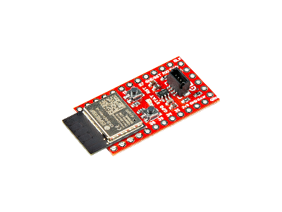
SparkFun ESP32 Qwiic Pro Mini
The SparkFun ESP32 Qwiic Pro Mini (DEV-23386) has an embedded ESP32-PICO-MINI-N8R2 module from Espressif with both 2.4GHz WiFi (802.11b/g/n) and Bluetooth (BT V4.2 BRBasic Rate/EDREnhanced Data Rate and BLEBluetooth Low Energy).
The ESP32-PICO-MINI-N8R2 module contains an Xtensa dual-core 32-bit 240MHz LX6 microprocessor, 8MB Flash, 2MB PSRAMPseudo Static Random Access Memory (PSRAM) is dynamic RAM with built-in refresh and address-control circuitry to make it behave similarly to Static RAM (SRAM)., and a built-in PCBPrinted Circuit Board antenna. The two CPU cores can be individually controlled and the CPU clock frequency is adjustable from 80MHz to 240MHz. The chip also has a low-power coprocessor that can be used instead of the CPU to save power while performing tasks that do not require much computing power, such as monitoring of peripherals.
The board has pin through holes for connecting peripherals such as an external SD card interface, capacitive touch sensors, ADC, DAC, Two-Wire Automotive Interface, Ethernet, high-speed SPI, UART, I2S, and I2C. The board includes a QwiicQwiic connectors are SparkFun's name for 4-pin JST SH connectors with 1.0mm pitch. These connectors were implemented on SparkFun boards to make it easy to plug-n-play various sensors and devices without soldering and wiring. Qwiic is cross-compatible with Adafruit's STEMMA QT connectors. connector for use with Qwiic sensors or modules. The Qwiic I2C data and clock lines are tied to 2.2kΩ pull-up resistors.
There are two buttons on the board: Reset and Boot. The reset (RST) button allows users to reset the program running on the module without unplugging the board. The Boot Button allows the user to manually put the board into Bootloader Mode. Two onboard LEDs, Power (Red) and STAT (Blue), show the user that power has been appropriately supplied to the board and the status of the data transfer.
An onboard AP2112K Voltage Regulator ensures that the appropriate voltage is provided to the various components of the board. The AP2112K has a max input voltage of 6V. The sleep current of the ESP32 chip is less than 5μA, making it suitable for battery-powered applications.
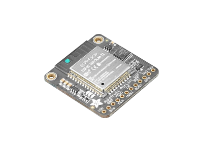
Adafruit Airlift ESP32
The Adafruit Airlift ESP32 WiFi Co-Processor Breakout Board (PID 4201) has an ESP-WROOM-32 module with 2.4GHz WiFi (802.11IEEE 802.11 is a set of protocol standards that define communication for a Wireless Local Area Network (WLAN). In order for WiFi to work between different devices, they all need to agree on how they are going to communicate. The current version of the standard is IEEE 802.11-2007, with many amendments such as 802.11a, 802.11b, 802.11g, and 802.11n.b/g/n/e/i) and Bluetooth (Classic/BLEBluetooth Low Energy) on a PCBPrinted Circuit Board with level shifting circuitry, a 3.3V regulator, and an SPISerial Peripheral Interface interface with a tri-state chip for MOSIMaster Out Slave In (MOSI) is the SPI data output line from the master device so you can share the SPISerial Peripheral Interface bus with other devices.
The ESP-WROOM-32 module has an integrated TCP/IPTCP/IP is a suite of internet communication protocols. TCP (Transmission Control Protocol) is responsible for establishing reliable, ordered data delivery, and handling congestion control, while IP (Internet Protocol) focuses on routing packets of data to their destination. protocol stack that can give your microcontroller access to your WiFi network with the latest TLSTransport Layer Security/SSLSecure Sockets Layer encryption (it has root certificates pre-burned in). Having WiFi managed by a separate processor from your microcontroller means your code is simpler, you don't have to cache socket data, or compile in and debug an SSL library.
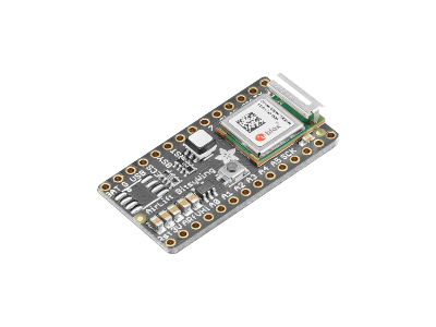
The Adafruit Airlift Bitsy ESP32 WiFi Co-Processor Breakout Board (PID 4363) has an integrated TCP/IPTCP/IP is a suite of internet communication protocols. TCP (Transmission Control Protocol) is responsible for establishing reliable, ordered data delivery, and handling congestion control, while IP (Internet Protocol) focuses on routing packets of data to their destination. protocol stack that can give your ItsyBitsy or other microcontroller access to your WiFi network with the latest TLSTransport Layer Security/SSLSecure Sockets Layer encryption (it has root certificates pre-burned in).
This breakout board has a u-blox NINA-W102 module with an integrated ESP32-D0WDQ6-V3 microcontroller (240MHz Dual-Core CPU, 2MB flash memory) that has 2.4GHz WiFi (802.11IEEE 802.11 is a set of protocol standards that define communication for a Wireless Local Area Network (WLAN). In order for WiFi to work between different devices, they all need to agree on how they are going to communicate. The current version of the standard is IEEE 802.11-2007, with many amendments such as 802.11a, 802.11b, 802.11g, and 802.11n.b/g/n) and Bluetooth (Classic/BLEBluetooth Low Energy) and an SPISerial Peripheral Interface interface using a tri-state chip for MOSIMaster Out Slave In (MOSI) is the SPI data output line from the master device so you can share the SPISerial Peripheral Interface bus with other devices. The u-blox NINA-W102 is the same processor used on the Arduino Uno WiFi Rev2 and Arduino Nano 33 IoTInternet Of Things microcontroller boards. The Airlift board also has an RGBRed Green Blue LEDLight Emitting Diode that you can control with programming.
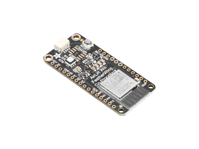
The Adafruit Airlift FeatherWing ESP32 WiFi Co-Processor Breakout Board (PID 4264) has an integrated TCP/IPTCP/IP is a suite of internet communication protocols. TCP (Transmission Control Protocol) is responsible for establishing reliable, ordered data delivery, and handling congestion control, while IP (Internet Protocol) focuses on routing packets of data to their destination. protocol stack that can give your Feather or other microcontroller access to your WiFi network with the latest TLSTransport Layer Security/SSLSecure Sockets Layer encryption (it has root certificates pre-burned in).
This breakout board originally included a ESP-WROOM-32 module, but as of April 24, 2023, Adafruit updated the PCBPrinted Circuit Board with the smaller ESP32-Mini-1 module. Both of these board versions have 2.4GHz WiFi (802.11IEEE 802.11 is a set of protocol standards that define communication for a Wireless Local Area Network (WLAN). In order for WiFi to work between different devices, they all need to agree on how they are going to communicate. The current version of the standard is IEEE 802.11-2007, with many amendments such as 802.11a, 802.11b, 802.11g, and 802.11n.b/g/n) and Bluetooth (Classic/BLEBluetooth Low Energy), an SPISerial Peripheral Interface interface using a tri-state chip for MOSIMaster Out Slave In (MOSI) is the SPI data output line from the master device so you can share the SPISerial Peripheral Interface bus with other devices, and an RGBRed Green Blue LEDLight Emitting Diode that you can control with programming. The updated PCBPrinted Circuit Board comes with the Pinguin to make a legible silkscreen and a STEMMA QTSTEMMA QT ('cutie') connectors are Adafruit's name for 4-pin JST SH connectors with 1.0mm pitch. These connectors were implemented on Adafruit boards to make it easy to plug-n-play various sensors and devices without soldering and wiring. The STEMMA QT (JST SH) are a smaller connector than the STEMMA (JST PH) that do not fit on smaller boards. STEMMA QT is cross-compatible with SparkFun Qwiic connectors. connector.
DFRobot Gravity ESP32
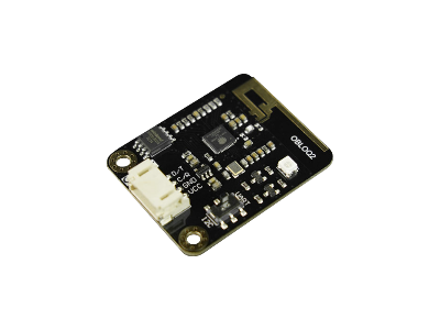
The DFRobot Gravity WiFi IoTInternet Of Things Module (SKU: TEL0126) has an integrated TCP/IPTCP/IP is a suite of internet communication protocols. TCP (Transmission Control Protocol) is responsible for establishing reliable, ordered data delivery, and handling congestion control, while IP (Internet Protocol) focuses on routing packets of data to their destination. protocol stack that can give your microcontroller access to your WiFi network.
The current version of this board comes with an ESP32-D0WD-V3 2.4GHz WiFi (802.11IEEE 802.11 is a set of protocol standards that define communication for a Wireless Local Area Network (WLAN). In order for WiFi to work between different devices, they all need to agree on how they are going to communicate. The current version of the standard is IEEE 802.11-2007, with many amendments such as 802.11a, 802.11b, 802.11g, and 802.11n.b/g/n) and Bluetooth (Classic/BLEBluetooth Low Energy) microcontroller on a PCBPrinted Circuit Board with a Winbond W25Q32JV 4MB SPISerial Peripheral Interface Flash memory chip, 5V to 3.3V level shifting circuitry, 3.3V regulator, and a switchable UARTUniversal Asynchronous Receiver-Transmitter/I2CInter-Integrated Circuit. Also referred to as IIC or I2C. Gravity interface (with a toggle switch on the side of the board).
This module supports multiple programming platforms, such as MakeCode, Mind+, and Arduino IDEIntegrated Development Environment (IDE) is a software application that helps develop software code efficiently., and can also be used on various popular IoT platforms like Easy IoT, IFFTTT, ThingSpeak, and SIoT.
ATWINC1500
The ATWINC1500 from Microchip is a low power 2.4GHz 802.11b/g/n IoTInternet Of Things WiFi module that integrates a Cortus APS3 32-Bit processor with 4MB SPI Flash memory, PAPower Amplifier, LNALow Noise Amplifier, transmit-receive switches, power management, and either a built-in PCB antenna or uFL connector for an external antenna. This module provides SPI ports to interface with a host controller.
| Module | Chip | Description | Datasheet |
|---|---|---|---|
|
Microchip ATWINC1500-MR210PB |
ATWINC1500 SoC
|
|
ATWINC15x0-MR210xB Datasheet
(PDF) |
|
Microchip ATWINC1500-MR210UB |
ATWINC1500 SoC
|
Alternative to the ATWINC1500-MR210PB module that has a uFL connector for an external antenna.
|
ATWINC15x0-MR210xB Datasheet
(PDF) |
Adafruit Airlift ATWINC1500
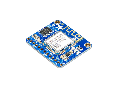
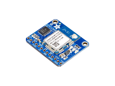
The Adafruit ATWINC1500 WiFi Breakout Board (PID 2999) has an integrated TCP/IPTCP/IP is a suite of internet communication protocols. TCP (Transmission Control Protocol) is responsible for establishing reliable, ordered data delivery, and handling congestion control, while IP (Internet Protocol) focuses on routing packets of data to their destination. protocol stack that can give your microcontroller access to your WiFi network with TLSTransport Layer Security/SSLSecure Sockets Layer encryption support. Having WiFi managed by a separate processor from your microcontroller means your code is simpler, you don't have to cache socket data, or compile in and debug an SSL library.
This breakout board has a Microchip ATWINC1500-MR210PB processor for 2.4GHz (802.11b/g/n) WiFi with a UARTUniversal Asynchronous Receiver-Transmitter/SPISerial Peripheral Interface interface, level shifting on all the input pins so you can use it with 3V or 5V logic, a 3.3V voltage regulator that can handle 300mA spikes and lets you power from 3.3V to 5.5V DC, and three on-board LEDLight Emitting Diodes that light up when connected to an SSIDService Set Identifier (SSID) is a unique sequence of characters that uniquely names a Wi-Fi network. A SSID is sometimes referred to as a network name. or transmitting data and you can also control.
Currently the Atmel supplied library works great with Arduino M0 and M4 but does not work on Uno (ATmega328P) and may not work on other Arduinos.
Adafruit also has a version of this board (PID 3060) with a uFL connector where you can hookup an external antenna. This version of the board uses a different module, the Microchip ATWINC1500-MR210UB, but has the same functionality as the ATWINC1500-MR210PB processor in the PCB antenna board version.
Conclusion
This overview covered different WiFi modules as stand-alone devices that can be wired to a microcontroller board, USB Serial Adapter, or SBCSingle Board Computer. WiFi modules can also be mounted to a PCB development board with extra features that make it more convenient to use, such as a USB interface, voltage regulator, power and logic 5V to 3.3V voltage level converters, reset and boot buttons, LEDLight Emitting Diodes, and more I/OInput/Output pins.




(0) Comments
Sign in to leave a comment
Sign In