Data Acquisition Overview
Updated: 06Aug2024 01:12:36 UTC 2024-08-06T01:12:36Z
Rating: (0 reviewsThis article has not been rated yet)
Data Acquisition (DAQData Acquisition) is the process of converting physical measurements into digital data bits that can be transferred to computer in order to be stored, analyzed, and displayed. This overview covers the components of a DAQ system: computer interfaces, signals, data storage, and computer software.
The front end of a DAQ system consists of a transducer (sensor) that outputs an electrical signal that varies with the physical measurement (voltage, current, temperature, light, sound, etc.). Sensors can either output a digital or analog signal. If the sensor outputs a digital signal, then this is read in by a computer interface, such as a General Purpose Input Output (GPIOGeneral Purpose Input Output) or serial (UARTUniversal Asynchronous Receiver-Transmitter, I2CInter-Integrated Circuit. Also referred to as IIC or I2C., SPISerial Peripheral Interface) interface, and converted into numerical data bits for the computer. The logic voltage levels of the digital signal may need to be shifted to the appropriate level for the interface with external signal conditioning circuitry (Logic Level Converter). If the sensor outputs an analog signal, then it may need to be conditioned to an acceptable level for an Analog-to-Digital Converter (ADCAnalog-to-Digital Converter (ADC, A/D, or A-to-D)) to produce the numerical data bits for the computer.
Computer Interfaces
The transformation of an electrical signal from a sensor to numerical data bits can be performed by devices such as a microcontroller (MCUMicrocontroller Unit), USBUniversal Serial Bus Serial Adapter, or Single Board Computer (SBCSingle Board Computer) GPIOGeneral Purpose Input Output. This section will give an overview of these three devices.
Microcontroller Boards
The transformation from an electrical signal to numerical data bits can be performed by a microcontroller and transferred serially to a computer over USB as shown in the figure below. MCUs are a self contained micro-processing System On a Chip (SoCSystem On a Chip) that includes memory (RAMRandom Access Memory, Flash), timers, interrupts, ADCAnalog-to-Digital Converter (ADC, A/D, or A-to-D), and I/OInput/Output ports. This integrated system allows programming the MCU to control interfacing with external electronic devices. A Single Board Microcontroller (SBMSingle Board Microcontroller) has an MCU built onto a single PCBPrinted Circuit Board with the power conditioning circuit, reset, clock circuit, USB chip and connector, and maybe some I/O conditioning. The SBM utilizes the MCU in a way that is easy to setup and interface to: plugging in power, USB to computer connection, loading software, and I/O connections.
Arduino Uno
The most well known microcontroller is the Arduino Uno Rev3 shown in the figure below. This board is typically used for quick prototyping, making it easy to plug in a power supply into the barrel jack or by USB, a data line from the computer to the USB connector, and input devices to the I/O port. The I/O on this board is 5V, making it convenient to work with external 5V devices. A hardware overview of the Arduino Uno R3 that covers Board Layout, Pinout, Power, Digital I/O, Analog Inputs, and Specifications is provided below.

Created:
07Apr2023 18:18:45 UTC
2023-04-07T18:18:45Z
Updated:
18Aug2024 02:33:48 UTC
2024-08-18T02:33:48Z
Rating:
(0 reviewsThis article has not been rated yet)
The Arduino Uno R3 is a microcontroller board based on the Atmega238P MCU that is designed for prototyping. This is a hardware overview of the board that covers:
- Specs
- Board Layout
- Different ways of powering the board and output power
- Digital I/O, Analog Inputs, and Communication Interfaces (UART/I2C/SPI)
Arduino Nano
The Arduino Nano shown in the figure below has a smaller footprint than the Arduino Uno and is breadboard friendly. This board consumes less power than the Arduino Uno, making it more suitable to embed into projects. The I/O on this board is 5V, like the Uno, making it convenient to work with external 5V devices. A hardware overview of the Arduino Nano that covers Board Layout, Pinout, Power, Digital I/O, Analog Inputs, and Specifications is provided below.

Created:
20Nov2023 19:40:22 UTC
2023-11-20T19:40:22Z
Updated:
18Aug2024 04:04:37 UTC
2024-08-18T04:04:37Z
Rating: (0 reviewsThis article has not been rated yet)
The Arduino Nano is a small breadboard-friendly microcontroller board based on the ATmega328 MCU. This is a hardware overview of the board that covers:
- Specs
- Board Layout
- Different ways of powering the board and output power
- Digital I/O, Analog Inputs, and Communication Interfaces (UART/I2C/SPI)
- Accessories
Raspberry Pi Pico
The RPiRaspberry Pi Pico, shown in the figure below, is another popular microcontroller with a small footprint. Like the Arduino Nano, the Pico is breadboard friendly and is low power. The I/O on this board is 3.3V, so external 5V devices need to be stepped down to be compatible with this board. A hardware overview of the RPi Pico microcontroller board that covers Board Layout, Pinout, Power, Digital I/O, Analog Inputs, and Specifications is provided below.

Created:
09Apr2023 02:58:19 UTC
2023-04-09T02:58:19Z
Updated:
18Aug2024 08:09:36 UTC
2024-08-18T08:09:36Z
Rating: (0 reviewsThis article has not been rated yet)
Overview of the Raspberry Pi Pico microcontroller board that covers specs, board layout, and power.
Common microcontrollers are the ATMega, RP2040, SAMD, STM32, and ATtiny. These microcontrollers come in different boards, as shown in the product listings below.


More details on the internal components of a microcontroller (CPUCentral Processing Unit, I/O Ports, Memory, Timers/Counters, Interrupts, and more) are in the Microcontrollers article.

Created:
25Sep2022 22:10:38 UTC
2022-09-25T22:10:38Z
Updated:
17Aug2024 20:57:54 UTC
2024-08-17T20:57:54Z
Rating:
(0 reviewsThis article has not been rated yet)
Overview of microcontrollers with a comparison of different MCUs covering CPU, Memory, I/O Ports, Timers, Interrupts, and System Bus.
USB Serial Adapters
There are sensors and external ADCAnalog-to-Digital Converter (ADC, A/D, or A-to-D) modules that output digital signals with a standard serial communication protocols like UARTUniversal Asynchronous Receiver-Transmitter, I2CInter-Integrated Circuit. Also referred to as IIC or I2C., and/or SPISerial Peripheral Interface. USB Serial Adapters can be used as a computer interface, converting the standard communication signal to USB protocol in order to transfer data to the computer over a USB cable. In order for the computer to detect and process the data, drivers must be installed on the computer. Some chip models, like FTDIFuture Technology Devices International, have drivers installed by default while with other chip models the drivers must be installed manually.
The USB Serial Adapter has a chip that processes the USB signals and applies the correct voltages for the serial output. Purchasing options for different chips is provided below.


Adapters can be specifically designed for either 3.3V or 5V serial and some can handle both. There are also adapters with a physical switch to manually change between 3.3V and 5V serial. They usually provide the USB 5V supply as an output to power low current devices. More details on USB serial adapters, including pin functions, I/O voltage levels, and device comparisons, can be found in the USB Serial Adapters article.

Created:
30Sep2022 02:52:47 UTC
2022-09-30T02:52:47Z
Updated:
19Aug2024 01:20:24 UTC
2024-08-19T01:20:24Z
Rating: (0 reviewsThis article has not been rated yet)
Overview of USB Serial Adapters including components, pin functions, I/O voltage levels, and a comparison of different devices.
Single Board Computer (SBC) GPIO
Another approach to data acquisition is to use a Single Board Computer (SBCSingle Board Computer) with an integrated GPIOGeneral Purpose Input Output that can be directly interfaced to with the digital/analog I/O pins or by using the data communication ports with UARTUniversal Asynchronous Receiver-Transmitter, I2CInter-Integrated Circuit. Also referred to as IIC or I2C., and SPISerial Peripheral Interface.
These boards usually take 3.3V digital input signals, but for analog signals an external ADCAnalog-to-Digital Converter (ADC, A/D, or A-to-D) module may be needed depending on the board. For example, the RPiRaspberry Pi 4B ADC shown in the figure below does not have an internal ADC, so an external ADC module is needed to handle analog signals.
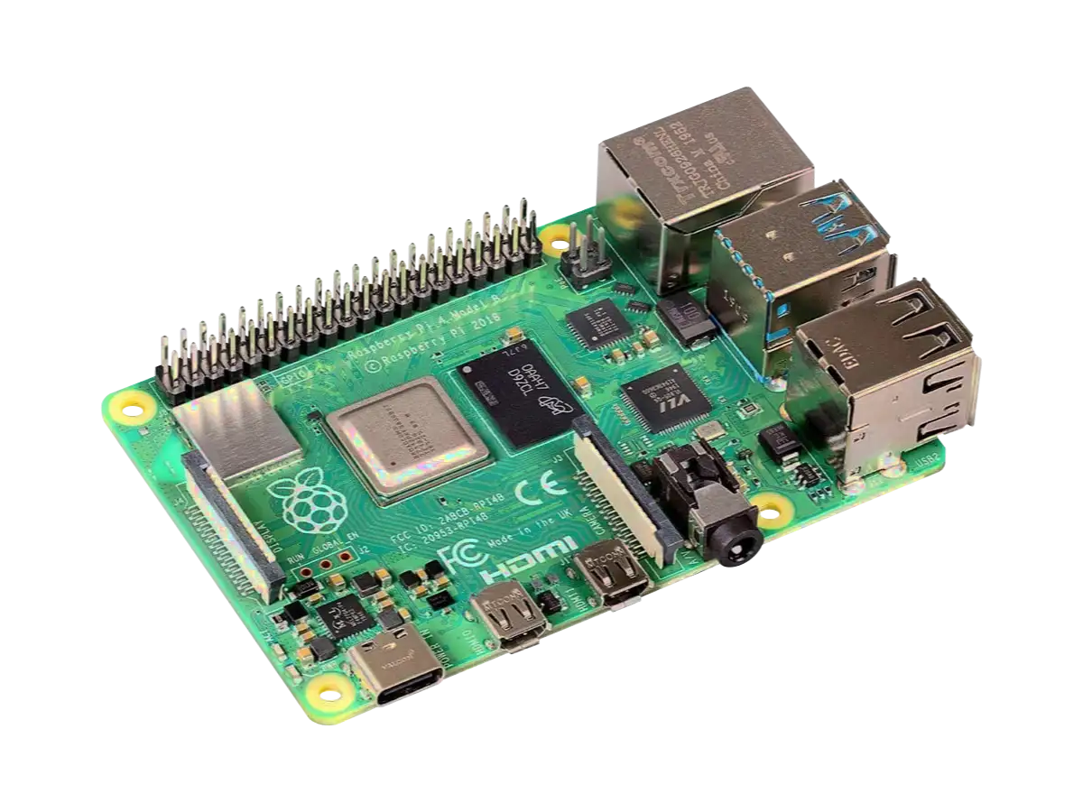
Created:
02Aug2023 01:36:49 UTC
2023-08-02T01:36:49Z
Updated:
17Aug2024 09:03:39 UTC
2024-08-17T09:03:39Z
Rating: (0 reviewsThis article has not been rated yet)
Raspberry Pi 4B (RPi4B) specs, board layout, components, I/O, and power.
The BeagleBone Black SBC shown in the figure below does have in interal ADC but is limited to a range of 0V to 1.8V.
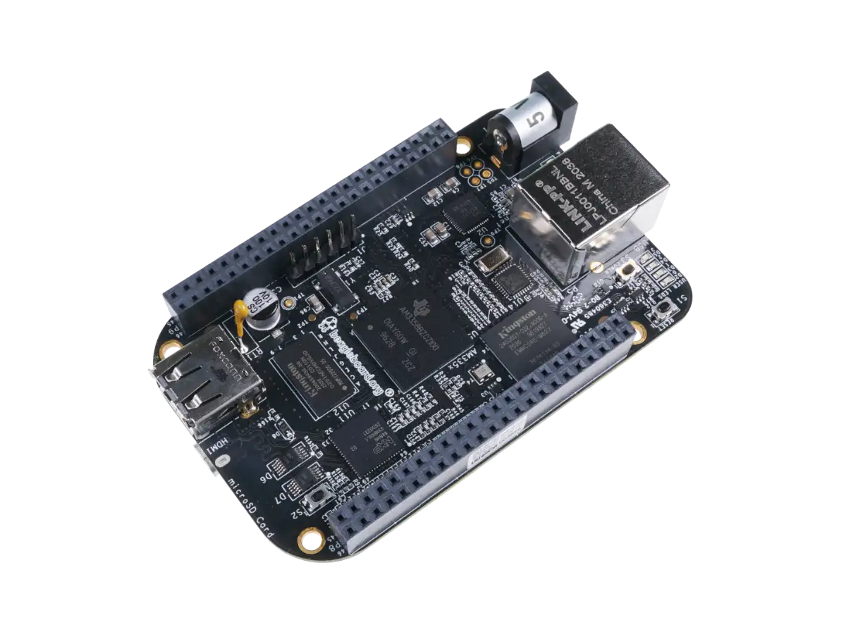
Created:
02Aug2023 08:00:15 UTC
2023-08-02T08:00:15Z
Updated:
17Aug2024 08:45:11 UTC
2024-08-17T08:45:11Z
Rating: (0 reviewsThis article has not been rated yet)
BeagleBone Black specs, board layout, components, I/O, and power.
Other popular SBCs include the Pine64, Odroid, Orange Pi, radxa Rock, and Libre. The product listings below show the different kinds of board products available.


An overview of SBCs with a comparison of different boards covering Processors, Memory, I/O Ports, Power, and Form Factor is provided below.

Created:
01Aug2023 23:05:26 UTC
2023-08-01T23:05:26Z
Updated:
16Aug2024 21:44:09 UTC
2024-08-16T21:44:09Z
Rating: (0 reviewsThis article has not been rated yet)
Overview of Single Board Computers (SBCs) with a comparison of different boards covering Processors, Memory, I/O Ports, Power, and Form Factor.
Digital Signals
A digital signal has discrete values of voltage over time. Binary or logic digital signals have two voltage values: one near the reference voltage (ground or zero volts) and the other at the supply voltage (Vs). The ground voltage is represented by binary digit bit 0 and the supply voltage is represented by the binary digit bit 1. This is illustrated in the figure below.
An introduction to digital signals covering its usage and properties of the waveform, bit ordering, voltage level encoding, and timing can be found in the Digital Signals article below.

Created:
19Mar2023 00:09:37 UTC
2023-03-19T00:09:37Z
Updated:
06Aug2024 03:10:58 UTC
2024-08-06T03:10:58Z
Rating: (0 reviewsThis article has not been rated yet)
What is a Digital Signal? What can you do with a digital signal? This article is an introduction to digital signals covering its usage and properties of the waveform, bit ordering, voltage level encoding, and timing.
Detecting Digital Voltage Levels
For most MCUs and SBCs, the voltage and current thresholds for low and high digital bits are usually found in the datasheet as:
- VIH:
- The lowest input voltage for logic high (1)
- VIL:
- The highest input voltage for logic low (0)
For the Arduino Uno R3 and Nano with an ATmega328P MCU, in section 28.2 DC Characteristics of the datasheet (PDF) it states the VIH = 0.6VCC and VIL = 0.3VCC, where VCC is the positive voltage rail supplied to the ATmega328P (VCC is the regulated DCDirect Current supply voltage needed to operate the ICIntegrated Circuit). With VCC = 5V, this gives VIH = 3V and VIL = 1.5V. This means that input voltages in the range of 0V - 1.5V will produce a logic low (0) and voltages in the range of 3V - 5V will produce a logic high (1). What about input voltages between 1.5V and 3V? This is an indeterminate voltage range and may produce either a logic low or high.
More details on the electrical characteristics of digital inputs into the GPIO of a microcontroller, including voltage level thresholds, floating inputs and pull resistors, and maximum voltage and current levels, can be found in the article below.

Created:
11Aug2022 19:03:45 UTC
2022-08-11T19:03:45Z
Updated:
06Aug2024 05:16:16 UTC
2024-08-06T05:16:16Z
Rating: (0 reviewsThis article has not been rated yet)
Covers the electrical characteristics of digital inputs into the GPIO of a microcontroller board or single board computer: voltage thresholds, leakage current, pull resistors, and maximum voltage and current levels.
Digital Signal Conditioning
When interfacing externally powered circuits to extract a digital signal, care must be taken on the compatibility of voltage levels and current between devices. Many MCUs and SBCs have their GPIO rated at 3.3V, so when used with an external 5V device a voltage shift is needed between the devices.
For example, on the Arduino Uno and Nano the input voltage levels must be between 0V and 5V with a recommended max current sink per pin of 20mA and an absolute max of 40mA. For the RPiRaspberry Pi Pico, the input voltage levels must be between 0V and 3.3V where the total sum current sunk into all of GPIO pins has a maximum rating of 50mA (see RP2040 Datasheet PDF, Section 5.2.3 Pin Specifications).
Resistor Voltage Divider
A typical scenario where voltage conversion is needed is using a 5V sensor with a 3.3V MCU or SBC to read the sensor. The simplest way to step the voltage down is to use a resistor voltage divider shown in the figure below.
Resistor values are chosen so their relative ratios divide the voltage from 5V to 3.3V. The resistor values are also chosen determine the amount of current and power being used, which must be within the resistor power ratings. Lower resistance in the divider will draw more current, whereas higher resistance will lower the current.


There are some limitations with the resistor voltage divider when interfacing digital circuits.
- They are unidirectional by only stepping down the voltage from one device to another. Two-way communication, such as with UARTUniversal Asynchronous Receiver-Transmitter/I2CInter-Integrated Circuit. Also referred to as IIC or I2C./SPISerial Peripheral Interface, requires bidirectional level shifting.
- The data transfer rate is reduced by higher resistor values in the circuit because it increases the rise time of the signal.
- There is no over-voltage protection beyond whatever margin is accounted for in the resistor values chosen.
Logic Level Converter or Shifter
The resistor voltage divider only provides a voltage drop in one direction. However, data communication lines need to be bidirectional and some data buses, like I2CInter-Integrated Circuit. Also referred to as IIC or I2C., need that level translated in both directions on a single line. The BSS138 N-channel MOSFETMetal-Oxide-Semiconductor Field-Effect Transistor (Datasheet PDF) allows bidirectional voltage conversion on the same line as shown in the figure below.
The BSS138 are surface mount components, but also come prepackaged into modules known as Logic Level Converters or Shifters. These modules have two different sides: one side for low voltage (LV) at 3.3V and the other side for high voltage (HV) at 5.0V. Examples of a Logic Level Converters from SparkFun and Adafruit are shown in the figures below.
The main advantage the BSS138 N-channel MOSFET Logic Level Converter modules have over the resistor voltage divider is the channels are bidirectional rather than unidirectional. However, on both types of circuits the maximum data transfer rate is reduced by higher resistor values in the circuit because it increases the rise time of the signal. The Logic Level Converter modules should work for speeds up to about 1MHz, sufficient for UART and I2C communication.
For faster communication protocols above 1MHz, such as SPISerial Peripheral Interface, a proper buffer/driver level shifter IC is recommended (4-wire SPISerial Peripheral Interface has no bidirectional pins, but 3-wire does). One such ICIntegrated Circuit is the TXS0108E by Texas Instruments with a maximum data rate of 110MbpsMegabits per second. This IC is available in a module as shown in the figure below.
The most common Logic Level Converter modules are the BSS138 FET, TXB, and TXS modules. There are also Level Shifter ICs available, such as the 74AHCT125 and 74LVC245.


More details on digital signal conditioning with different circuits and modules, including over-voltage protection and opto-isolation, can be found in the Interfacing Digital Inputs article.

Created:
27Mar2023 22:51:48 UTC
2023-03-27T22:51:48Z
Updated:
24Jun2024 08:11:19 UTC
2024-06-24T08:11:19Z
Rating: (0 reviewsThis article has not been rated yet)
Covers the electrical compatibility of a microcontroller board or single board computer with external devices: Voltage Dividers, Level Converters/Shifters, Over-Voltage Protection, and Electrical Isolation.
Analog Signals
Analog signals have a continuous range voltage and current values to represent information, but if you want to process that signal using using a microcontroller and/or computer, then you need a discrete digital representation. Measuring discrete samples from a continuous analog signal creates an effect called quantization as shown in the figure below.
The signal is quantized both in terms of time by sampling at discrete intervals and also in amplitude by its discrete digital representation. Any changes in the analog signal between samples points is lost in the digital data. How much the analog signal varies over time, the sampling rate (number of samples per unit time), and resolution (number of digital bits representing the data), are key factors that influence the accuracy when acquiring digital data.
Read more about analog signal waveform properties, bandwidth, and DC/AC coupling in the Analog Signals article.

Created:
12Oct2022 04:27:30 UTC
2022-10-12T04:27:30Z
Updated:
06Aug2024 20:38:51 UTC
2024-08-06T20:38:51Z
Rating: (0 reviewsThis article has not been rated yet)
What is a analog signal? What can you do with a analog signal? This article is an introduction to analog signals covering its usage and wave properties such as DC and AC components, frequency, and bandwidth.
Analog to Digital Conversion
Analog signals are converted to digital data using an Analog-to-Digital Converter (ADCAnalog-to-Digital Converter (ADC, A/D, or A-to-D)). Many low cost microcontrollers and some single board computers have ADCs built into them. The voltage ranges of these ADCs are typically the supply range (0V to 3.3V or 0V to 5V) and resolutions are usually 10-bit, 12-bit, or 16-bit.
The goal of the ADC is to accurately represent analog signals as digital data, a process that involves sampling, quantization, and encoding. There are a few different ways to achieve this, but one of the most common technique uses the analog input voltage to charge up an internal capacitor and then held to measure the time it takes to discharge across an internal resistor. The discharge time, determined by counting the number of clock cycles, is converted into digital representation of the original analog input sampled.
Sampling Rate
The sampling rate quantizes the analog signal in the time domain. How fast of an ADC sampling rate is needed depends on your application. Some applications require high sampling rates while others can use a low sampling rate. For example, high sampling rates are needed with the conversion of an audio signal: the human voice signal contains frequency components that span from 20Hz to 4kHz. Low sampling rates are used to take samples at intervals of several seconds, minutes, hours, or even days, such as measuring the temperature of your house or monitoring a battery level.
The general approach is to choose a minimum sampling rate that is at least double the highest frequency content of the signal from the Nyquist Theorem in order to render a faithful reconstruction of the original signal. In practice, as a rule of thumb, a minimum sampling rate of at least 5x to 10x the highest frequency content is chosen to give a decent representation of the original signal.
Resolution
An analog signal is quantized in amplitude by its discrete digital representation. The resolution of an ADC indicates the number of different discrete values it can produce over the allowed range of analog input values. This defines the smallest step size change that can be measured by the ADC, often referred to as quantization error.
Resolution can be expressed as the bit depth n where the number of discrete values available is 2n. For example, an ADC with a resolution of 10-bits can encode an analog input to one of 210 different levels from 0 to 1023.
Resolution can also be defined electrically in Volts. The change in voltage required to guarantee a change in the output level is called the Least Significant Bit (LSBThe Least Significant Bit (LSB) in a binary number is the bit that represents the smallest place value carrying the lowest weight. It is also sometimes referred to as the low-order bit or right-most bit due to the convention in positional notation of writing less significant digits further to the right.) voltage. The resolution of an ADC is equal to the LSB voltage as given in the figure below. For example, the Arduino Uno R3 microcontroller board has a 10-bit ADC with a voltage range of 5V by default, so the ADC resolution is 5V/210 ≈ 4.9mV per step.
Microcontroller ADCs
Most microcontrollers include an internal ADC with subset of GPIOGeneral Purpose Input Output pins that you can use to interface with the ADC. The ADC input pins are typically labeled with an 'A' in front of their name. For example, the analog input pins for the Arduino Uno R3 are labeled A0 through A5, the Arduino Nano pins are labeled A0 through A7, and the RPiRaspberry Pi Pico pins are labeled ADC0 through ADC2.
The most common ADC in MCUs is a SARSuccessive Approximation Register where an internal sample and hold S/HSample and Hold capacitor is charged to the input voltage (sample) and then disconnected (hold) to measure the time in number of clock cycles it takes to discharge across an internal resistor and zoom in on the correct ADC output.
The resolution of MCU ADCs typically range from 8-Bit to 12-Bit. For instance, the Arduino Uno R3 and Nano has a 10-bit ADC, whereas the RPiRaspberry Pi Pico ADC is 12-bit.
ADC ICs and Modules
There are many ADCs that are packaged in ICIntegrated Circuits and modules, ranging from 8-bit up to 24-bit resolution with I2CInter-Integrated Circuit. Also referred to as IIC or I2C. or SPISerial Peripheral Interface data interfaces. Some well known ADC ICs and modules are given below.


More details on MCU ADCs and standalone ICs and Modules, including their capabilities, pin functions, I/O voltage levels, and device comparisons, can be found in the Analog-to-Digital Converters article.

Created:
28Mar2023 18:02:04 UTC
2023-03-28T18:02:04Z
Updated:
06Aug2024 21:37:08 UTC
2024-08-06T21:37:08Z
Rating: (0 reviewsThis article has not been rated yet)
How Analog-To-Digital Converters (ADCs) work.
- ADC Specs: Sampling Rate, Resolution, and Channels
- Arduino Uno R3 and RPi Pico Microcontroller ADCs
- ADC ICs and Modules
Analog Signal Conditioning
Output signals from analog sensors are not always compatible with the input voltage and current range of ADCs. Signal Conditioning is the modification of a signal to prepare it for the next stage of processing. For ADC input, this signal modification typically involves scaling and/or shifting to the input range of the ADC as shown in the figure below.
The output of the sensor transducer is scaled (either amplified or attenuated) and shifted by a DC bias to the range of the ADC input. As an example, suppose a sensor has an output in the -5V to +5V range and the ADC input requires a range of 0V to 5V. The sensor output can be scaled by a factor of 0.5 to reduce it to the range of -2.5V to +2.5V. The signal now needs to be shifted by +2.5V DC to map it to the range of 0V to 5V for the ADC input. Front end circuitry with OpAmps and resistors can be used to amplify/attenuate/shift voltage levels. More details can be found in the Interfacing Analog Inputs article.

Created:
13Oct2022 04:06:22 UTC
2022-10-13T04:06:22Z
Updated:
07Aug2024 00:28:40 UTC
2024-08-07T00:28:40Z
Rating: (0 reviewsThis article has not been rated yet)
How do you reduce the analog voltage input within the ADC range? How do you shift negative voltages to the positive ADC range? How can you amplify small signals to increase your ADC resolution? This article covers analog input attenuation with voltage dividers, impedance buffers, and signal amplification.
Data Storage
Measured data can be stored temporarily or permanently within a microcontroller's memory or externally in an ICIntegrated Circuit, module, or computer.
MCU Internal Memory
Microcontrollers usually contain volatile memory, such as SRAMStatic Random Access Memory, and non-volatile memory, such as Flash and/or EEPROMElectrically Erasable Programmable Read-Only Memory. A description of each is given below.
- SRAMStatic Random Access Memory:
- Static Random Access Memory (SRAM) is a type of volatile memory, so its contents are lost if the microcontroller loses power. It is the working data space for storing transient data, such as variables, the heap, and the stack, that can be written to and read from during program execution.
- Flash:
- Flash is a type of non-volatile memory that can be read, erased, and written to, where its contents are retained if the microcontroller loses power. It is used to store programs (code) and also any "constant" data values.
- EEPROMElectrically Erasable Programmable Read-Only Memory:
- Electrically Erasable Programmable Read-Only Memory (EEPROM) is type of non-volative memory that holds data that needs to persist between software changes and power cycles. It can be erased and written to. It is useful for logging system malfunctions and fault data during program execution. It is also useful for storing special data or configuration data that must be retained during a power failure but might need to be changed periodically.
In most microcontrollers, RAM memory is usually smaller in size than flash memory because it costs more. RAM memory has lower latency (faster read/write) than flash memory. Some microcontrollers, like the RPiRaspberry Pi Pico, do not have EEPROM and rely entirely on Flash memory to store permanent data. While other microcontrollers, like the Arduino Uno, use the Flash memory store programs and rely on EEPROM for storing permanent data. The Microcontroller Memory article below has more details on the different kinds of memory in microcontrollers.

Created:
26Aug2023 18:25:37 UTC
2023-08-26T18:25:37Z
Updated:
07Aug2024 03:48:24 UTC
2024-08-07T03:48:24Z
Rating: (0 reviewsThis article has not been rated yet)
Covers the memory components of MCUs
- Volatile Memory (RAM)
- Non-Volatile Memory (Flash and EEPROM)
External Memory ICs and Modules
If more memory is needed for your microcontroller application, external memory ICIntegrated Circuits or modules are an option. These are available in different packages, memory size, interface protocol, page write capability (the amount of bytes per write), write speed, retention period, and endurance. Purchasing options for different external memory ICs and modules are given below.


A comparison of EEPROM, Flash, FRAMFerroelectric Random Access Memory, and SDSecure Digital removable miniaturized flash memory cards Cards can be found can be found in the External Memory Components article below.

Created:
29Mar2023 23:05:49 UTC
2023-03-29T23:05:49Z
Updated:
27Aug2024 06:44:44 UTC
2024-08-27T06:44:44Z
Rating: (0 reviewsThis article has not been rated yet)
External memory ICs and modules are available in different packages, memory size, interface protocol, page write capability (the amount of bytes per write), write speed, retention period, and endurance. Different types of memory devices and comparison between them are covered.
Computer Software
Software Interface
An SBCSingle Board Computer with an integrated GPIOGeneral Purpose Input Output can be directly interfaced to the digital/analog I/OInput/Output pins or by using the data communication ports with UARTUniversal Asynchronous Receiver-Transmitter, I2CInter-Integrated Circuit. Also referred to as IIC or I2C., and SPISerial Peripheral Interface. For the SBC software, you can use the programming language of your choice (Python, Rust, C/C++, Java, etc.) to interact with these ports.
On a PCPersonal Computer that does not have an integrated GPIOGeneral Purpose Input Output, you can communicate via USBUniversal Serial Bus with an external device that has a physical USB interface. The computer software then needs to open the USB device port to establish communication. Different software packages are available for USB device port communication. A popular choice in Python is the PySerial package that is open source code written and maintained by Chris Liechti with the functionality to access and communicate with the serial port from Python. PySerial automatically selects the appropriate backend whether you're running on Windows, OSX (Mac), Linux, BSDBerkeley Software Distribution (BSD) operating system (possibly any POSIXPortable Operating System Interface (POSIX) is a family of standards specified by the IEEE Computer Society for maintaining compatibility between operating systems compliant system) or IronPython. More details can be found in the Python PySerial I/O article below.

Created:
27Oct2022 23:29:36 UTC
2022-10-27T23:29:36Z
Updated:
07Aug2024 04:39:18 UTC
2024-08-07T04:39:18Z
Rating: (0 reviewsThis article has not been rated yet)
PySerial functional interface and how it works under the hood.
Computer Recording
Recording data onto a computer and opens up more capability for storage, data processing, analysis, and visualization. You could capture data onto the memory of an SBCSingle Board Computer directly with serial communication using UARTUniversal Asynchronous Receiver-Transmitter/I2CInter-Integrated Circuit. Also referred to as IIC or I2C./SPISerial Peripheral Interface or indirectly onto a PCPersonal Computer (laptop/desktop) from a microcontroller through USB. How to get data from the measuring device through USB to the computer and into long term storage takes some design considerations with the software running on both the computer and the device as shown in the figure below.
The computer software needs to open the device port to establish communication. If the device is an MCU
connected by USB to a Linux machine, the USB CDCUSB Communication Device Class ACMAbstract Control Model is used with the device
name /dev/ttyACM0. If a USB bridge adapter is used to connect to the
device, then these devices are named /dev/ttyUSB0,
/dev/ttyUSB1, etc. On a Windows PCPersonal Computer, the Device Manager will
show the MCU or USB adapter under the Ports COMCommunication & LPTLine Print Terminal as a USB Serial
Device.
The software would send commands to the device telling it how many measurement samples and how long to make those measurements (assuming an even sampling rate is desired). The device reads in the commands, interprets it, and starts making measurements (either digital or ADC) and stores the digitized results in a local array. This array of digital data is then copied to the serial communication buffer in the device to be transferred over USB to the computer. The computer reads in the USB data through the device port into RAM so the software can process the data (e.g., converting digital counts to volts). Once the data is processed it can be stored in a file and also make live plots for visualizing the data. The software can be setup to repeat this process and command the device to make more measurements if desired.
The timing of read/writes of the measurements and communication transfers should be carefully considered so processes don't clobber each other. The timing diagram shown in the figure below illustrates the relative processing times consumed by collecting data and communication transfers.
The communication times of sending a request and receiving data over USB should be minimized by selecting a high baud rate (this depends on the USB Serial chip of the device, where the reliability of data transfers can be an issue if the baud rate is too high). Most of the time spent on the device is usually needed to measure the samples, process the data (e.g., ADC), and store the results in a local array in RAM. Time is also consumed on the device when copying data out of RAM in order to transfer the data to the computer.
The measurement timing of the device needs to be determined. The sample period can be computed from the requested number of samples and requested length of time to take all the samples. However, the device needs to know how long to delay after each sample to start the next sample as shown in the figure below. This delay time not only depends on the sampling period, but also on the sample time of the device which can vary with an ADC. If the sample time varies significantly, then it can measured dynamically within the device's embedded software; otherwise a constant sample time can be used.
The requested number of samples and how long to make measurements needs to be within the capability of the device, which has limits on the memory capacity and how fast it can sample. Too many samples will exceed the memory on the device before handing that data over to the computer. Software error checking either in the computer or device should be included to ensure there is sufficient memory for the sample size requested. If the sample rate is too high, the device can interrupt its own digital/analog read and processing. Error checking on the requested sampling rate involves determining the sampling time of the device and ensuring this doesn't exceed the time between samples.
The amount of time for the computer to read in and process the data is usually of concern if fast repeated requests for samples is needed (e.g., an oscilloscope). The computer processing time can be minimized by enhancing the performance of software programming and utilizing the hardware capabilities (e.g., multiple CPUCentral Processing Unit cores with threading).
Data Visualization
Once data is acquired onto a computer it can be visualized in plots or tables for analysis. Plots can be made from fully recorded data or created in real-time as the incoming data becomes available. You can use the plotting routines that comes with most spreadsheet software (LibreOffice Calc, Excel, etc.) or create plots programmatically with the language of your choice.
In Python, the Matplotlib library can be used to plot fully recorded data or create live plots. This is covered in more detail in the article Live Plotting Data with Python using Matplotlib.
Created:
31Oct2022 07:19:06 UTC
2022-10-31T07:19:06Z
Updated:
07Aug2024 06:05:49 UTC
2024-08-07T06:05:49Z
Rating: (0 reviewsThis article has not been rated yet)
How to plot real-time data with Python using Matplotlib.


(0) Comments
Sign in to leave a comment
Sign In