Measuring Current
Updated: 04Aug2024 23:08:40 UTC 2024-08-04T23:08:40Z
Rating: (0 reviewsThis article has not been rated yet)
An Ammeter (or Multimeter) is often used to measure current in electronic circuits to test or troubleshoot devices. If you want to include current measurements in your application, a handheld multimeter would not be suitable due to its large size, cost, power consumption, and most of them do not have a data logging feature.
Current measurements can be made with a current sensor connected to an ADC in a microcontroller, where the data can be transferred to a computer to be stored, processed, and visualized. This is useful for monitoring the power consumption of devices. Performing current measurements for data acquisition requires some familiarity of what current is, the difference between DC and AC signals, and the capabilities of different current sensing techniques such as using a shunt resistor, Hall Effect sensor, or Current Transformer (CTCurrent Transformer).
Current
An electric current is a flow of charged particles. Electric current in a wire is a measure of the quantity of charge passing any point of the wire per unit of time. Voltage, or Electromotive Force (EMFElectromotive Force (EMF) is the potential difference or voltage in energy per unit charge, generated by a source of electrical energy, such as a battery, photovoltaic cell, or generator.), is the driving force behind electric current. The cause of current flow can be from electrochemical processes in cells and batteries, magnetic fields (electromagnetic induction), thermal energy (thermoelectricity), mechanical energy from pressure or vibration (piezoelectricity), or static charge build-up and discharge.
In the International System of Units (SIThe International System of Units (SI) is the modern form of the metric system and the world's most widely used system of measurement employed in science, technology, industry, and everyday commerce.), electric current is expressed in units of Ampere (sometimes called an "amp" or the symbol A), named after French mathematician and physicist André-Marie Ampère (1775-1836) who studied electromagnetism and laid the foundation of electrodynamics. One amp is equal to one Coulomb (C) of charge moving past a point per second. The amount of amps can be measured going through, into, or out of circuit components, power supplies, sensors, and other electronic devices.
The most common way to measure current in a circuit is to break the circuit open and insert an ammeter in series (in-line) with the load so that all current flowing through the circuit must also go through the meter (or sensor). Another way of measuring current that does not require breaking the circuit is by detecting the external magnetic field produced by the current through the wire, such as with some Hall Effect sensors and Current Transformers.
An electric load is a component of a circuit that consumes electricity. A load can be light bulbs, appliances, devices, or electronic components such as a resistor. The load of a circuit is inversely proportional to current flow: bigger loads lower the current in a circuit. If no significant load is present in a closed circuit, a short circuit will result and potentially cause damage to the power source and ammeter.
Signals
Direct Current (DC) and Alternating Current (AC) are two main types of signals that are have their own properties and are measured by different types of current sensors.
DC Current Signals
Direct Current (DC) signals are defined as a one directional flow of current in a circuit. A DC signal has only one electrical polarity of voltage and current, which are either constant, zero frequency, or variable with a slowly varying local mean value. Three examples of DC voltage or current signals are shown in the figure below.
AC Current Signals
Alternating Current (AC) signals are defined by a current flow that changes direction periodically. The voltage and current in an AC signal changes polarity and can be out of phase. The most basic type of AC signal is a sinusoidal waveform shown in the figure below.
An AC signal is characterized by its amplitude, period, frequency, phase, and DC offset.
- Amplitude:
- The height of the signal from a reference level such as zero.
- Period:
- The amount of time (T) the signal completes one cycle.
- Frequency:
- The number of repetitions (cycles) that occur in a specified amount of time, expressed in cycles/second or Hertz (Hz). A signal's frequency is inversely related its period: f = 1/T.
- Phase:
- The amount of horizontal shift relative to time zero, usually expressed in degrees or radians. A phase shift of 360 degrees (or 2π radians) gives the same wave with no shift.
- DC Offset:
- The amount of vertical shift in the waveform, where the waveform has DC and AC components as shown in the figure below.
Shunt Resistor
A common way to measure current is to convert it into a voltage by inserting a precision shunt resistor within the circuit in series with the load. The shunt resistor creates a voltage across it that is proportional to the current flow. The shunt resistance is often very low, on the order of milliohms, so it does not steal much of the supply voltage delivered to the load, affect the current flow being measured, and waste power from heat dissipated by the resistor. This means the voltage across the shunt resistor is also quite small, and often requires amplification before being read by an ADCAnalog-to-Digital Converter (ADC, A/D, or A-to-D).
High/Low Side Sensing
There are two ways the shunt resistor can be placed in series with the load, called low-side sensing or high-side sensing. In low-side sensing, the shunt resistor (RS) is placed between the ground terminal of the power supply and the ground terminal of the load as shown in the figure below.
In high-side sensing, the shunt resistor is placed between the positive terminal of the power supply and the supply input of the load as shown in the figure below.
Low-side sensing is preferred for measuring current in applications with very high voltages/current or where the supply voltage may be prone to spikes or surges. One disadvantage of low-side sensing is its inability to detect ground faults (a short to ground) within the load. Another problem with low-side sensing is ground loop issues that can result in noise and interference, due to the shunt resistor placed between the load and ground where the load may not be at the exact same ground potential as the rest of the circuitry.
Shunt Resistor Specs
When selecting a current sense shunt resistor, key specs include resistance, power rating, tolerance, temperature coefficient, and terminal type.
- Resistance:
- The resistance is the primary characteristic of a current sense resistor, usually expressed in Ohms (Ω). The resistance value determines the voltage drop across the resistor and how much the current is influenced. It is chosen based on the desired measurement range and accuracy. A lower resistance value is used for higher currents and a higher resistance value is used for lower currents.
- Power Rating:
- The power rating, typically specified in Watts (W), determines the maximum amount of power the resistor can safely handle without overheating or causing damage to the resistor.
- Tolerance:
- A resistor's tolerance, expressed as a percentage (%), indicates the maximum deviation from the nominal resistance value. The resistor's tolerance affects the accuracy of the current measurement. Ordinary resistors have tolerances ranging from 1% to 10%, whereas current shunt resistors have lower tolerances ranging from 1% to 0.1%.
- Temperature Coefficient:
- The Temperature Coefficient of Resistance (TCRThe Temperature Coefficient of Resistance (TCR) of a resistor is a measure of how much the resistance changes in response to a change in temperature, usually expressed in parts per million per degree Celsius (ppm/°C).) of a resistor is a measure of how much the resistance changes in response to a change in temperature, usually expressed in parts per million per degree Celsius (ppm/°C) or for higher TCR values a percentage per degree Celsius (%/°C). Lower TCR values are needed for accurate current measurement because large currents heat up the resistor and any significant changes in the resistance results in errors in the current measurements. Ordinary resistors have a TCR in the thousands ppm/°C, but current sense resistors are much lower in the tens to hundreds ppm/°C. Using a snip of copper wire may seem like a good way to get a milliohm sense resistor at almost no cost, but its TCR is around 4000 ppm/°C (0.4%/°C) which is orders of magnitude inferior to current sense resistors.
- Terminal Type:
- Current sense resistors are typically 2-terminal or 4-terminal. The 2-terminal setup is less accurate due to the extra resistance and TCR effects in the resistor leads and combined connections of both the application circuit and current sense at the resistor terminals. The 4-terminal setup (also known as Kelvin Sensing) is more accurate by providing two terminals for the current path of the application circuit and a second pair of terminals for voltage detection used in current sensing. The 4-terminal setup ensures that only the voltage across the resistor is measured by not including the resistance of the resistor's leads and combined connections.
Determining the resistance value of a current sense resistor has trade-offs. A larger resistor provides better accuracy and resolution for lower currents as it increases the dynamic range, improves the signal-to-noise ratio (SNR), and minimizes the effects of the offset. However, a higher resistance value results in a larger voltage drop that steals more of the supply voltage that can be delivered to the load and power is wasted from more heat dissipated by larger resistors.
The current sense resistance can be determined from Ohm's Law using either the desired range or resolution of the resistor's output voltage and input current. For the range, the current sense resistance can be determined from the ratio of the full-scale differential voltage to the maximum expected current. Current sense amplifiers have a full-scale differential voltage in the range of 10mV to 100mV, but are more commonly found around 100mV. For a full-scale differential voltage of 100mV and expected current range up to 100mA, the value of the current sense resistance is (100mV)/(100mA) = 1Ω. The resistance also tells us how much the voltage changes on the resistor for changes in current, where 1Ω provides 1mV/1mA. This means the current sense resistance can also be determined from the ratio of the resolution of your voltage measuring circuit to the desired minimum resolution of your current measurements.
The following table lists the resistance value ranges for different current ranges using a full-scale differential voltage of 100mV. Higher resistance values are used for lower currents and lower resistance values are used for higher currents.
| Current Category | Current Range |
Resistance Range |
|---|---|---|
| Very Low Currents | 1mA - 10mA | 100Ω - 10Ω |
| Low Currents | 10mA - 100mA | 10Ω - 1Ω |
| Medium Currents | 100mA - 1A | 1Ω - 0.1Ω |
| Medium-High Current | 1A - 10A | 0.1Ω - 0.01Ω |
| High Currents | 10A - 100A | 0.01Ω - 1mΩ |
Shunt Resistor Amplifier
Current sense shunt resistors typically have a very low resistance, which means the voltage across the resistor is quite small and requires amplification before being read by an ADC.
Normal differential amplifiers and operational amplifiers do not amplify very small amounts of voltage very well, have a lower common-mode rejection, and their inputs are limited by the power supply rails. Current sense amplifiers are special-purpose amplifiers designed to amplify very small voltages (10mV to 100mV) in the presence of very large common-mode voltages, have high common-mode rejection, and can withstand a wider input range than the power supply rails.
When selecting a current sense amplifier, key specs include Current Direction, Common Mode Range, CMRRCommon-Mode Rejection Ratio, Offset Voltage, Gain, Bandwidth, and Accuracy. Other factors to consider are high/low side current sensing, power supply range, current consumption, size, and operating temperature range.
- Current Direction:
- Some amplifiers can only measure current in one direction (unidirectional/unipolar) from the negative terminal (-) to positive terminal (+), such as the INA169 IC. However, there are amplifiers that have the capability to measure current in both directions (bidirectional/bipolar), such as the INA282 IC.
- Common Mode Range:
- The common mode range is the DC voltage range at the input of the amplifier with respect to ground, which could be wider than the supply range. For example, the INA282 IC has a common mode range of -14V to +80V and a supply range of +2.7V to +18V DC. Unlike normal amplifiers, current sense amplifiers are designed to withstand a much higher or lower pin voltage than the power supply.
- Common-Mode Rejection Ratio (CMRR):
- Defined as the ratio of the differential voltage gain to the common-mode voltage gain (ADIF/ACOM), usually expressed in dBDecibel (dB) used to express the ratio of two physical quantities such as power, sound intensity, sound pressure, voltage, and current on a logarithmic scale. [20log10(ADIF/ACOM)] or a voltage ratio [μV/V]. This refers to the error in balancing the inputs that quantifies the ability of the amplifier to reject common-mode signals on both inputs. A higher CMRR value means better amplifier performance at rejecting noise and interference. A CMRR of 80dB or higher typically ensures that the amplifier is less sensitive to common-mode voltage errors.
- Offset Voltage:
- This is the voltage measured across differential amplifier inputs when both positive and negative inputs are at the exact same voltage. Ideally this voltage would be zero, but in reality it is always a non-zero voltage. The offset voltage is typically in the mV range, but can be as low as 10μV. Offset voltages can also drift over time and operational temperature.
- Gain:
- The amplifier gain is the ratio of the output voltage to the input voltage across the shunt resistor. Current sense amplifiers have different gains ranging from 0.125 V/V to 1000 V/V. There are also different options for current sense amplifier ICs, such as a fixed gain (INA282) or setting the gain with an external resistor (INA169). Gains can also drift over time and operational temperature.
- Bandwidth:
- This is the range of frequencies over which the amplifier can accurately amplify the input signal. For example, the INA282 IC has a bandwidth of 10kHz. If the amplifier outputs a current where an external resistor is used to convert the output to voltage, the bandwidth depends on the resistor's value (e.g., the INA169 IC has a bandwidth of 440kHz for 10kΩ for and 220kHz for 20kΩ).
- Accuracy:
- The accuracy of a current sense amplifier, expressed as a percentage (%), is how close the amplifier measures the input current compared to the actual current. For example, an accuracy of ±1% means that the amplifier will produce an output signal that is within ±1% of the true input current. Errors can be caused by various factors, including gain non-linearity and drift, offset error and drift, common-mode voltage error, and temperature. Electrical noise and interference can also affect the amplifier's output, causing errors in the measurement.
Shunt Resistor Monitors
Two examples of a shunt resistor current monitor ICIntegrated Circuits with an analog output are the INA169 and INA282. The INA169 only has high-side sensing and can only measure currents in one direction, whereas the INA282 has either high or low side sensing and can measure bidirectional currents. The INA169 outputs an analog current that requires an external resistor to set the gain and convert it to an analog voltage output. The INA282 has an analog voltage output with a fixed gain of 50 V/V (there are other ICs in the INA28x series with higher gains).
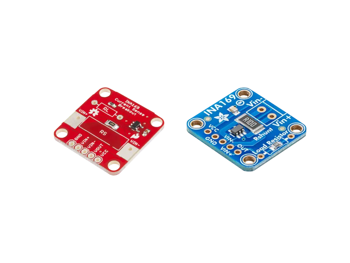
The INA169 IC has breakout boards available from SparkFun and Adafruit, shown in the figure below, with external circuitry and pin through holes to make it easy to interface to. Generic breakout boards are also available for the INA169 IC.

Created:
12Apr2023 21:46:48 UTC
2023-04-12T21:46:48Z
Updated:
07May2024 23:46:11 UTC
2024-05-07T23:46:11Z
The INA169 High-Side DC Current Shunt Sensor modules output an analog voltage proportional to the input current that goes through a shunt resistor.
- SparkFun and Generic Modules (3.5mA to 35mA)
- Adafruit and Generic Modules (0.5A to 5A)
The INA282 has generic breakout boards available with external circuitry and pin through holes to make it easy to interface to. The module shown below has a simple board layout with only three components: the INA282 IC, power supply bypass capacitor, and a 0.1Ω 1% tolerance shunt resistor.

Created:
03Jun2024 06:39:11 UTC
2024-06-03T06:39:11Z
Updated:
03Jun2024 07:09:09 UTC
2024-06-03T07:09:09Z
The INA282 High-Side or Low-Side Bidirectional DC Current Shunt Sensor modules output an analog voltage proportional to the input current that goes through a shunt resistor.
Hall Effect
The Hall Effect is a phenomenon in which a potential difference (the Hall voltage) is produced in a conductor (or semiconductor) when it is carrying a current perpendicular to a magnetic field. This effect was discovered by the American physicist Edwin Herbert Hall in 1879.
The Hall Effect can be used to measure current. When current (I) flows through a conductor, a magnetic field (B) is created. If a biased Hall Effect element is placed near the current conductor, the magnetic field produces a small Hall voltage (VH) across the element. This Hall voltage is amplified to provide a voltage output that can be read by an ADC or voltmeter. Since there is a linear relationship between the output voltage and the current measured, the value of the current can be computed (the amplified voltage output is proportional to the Hall voltage, which is proportional to the strength of the magnetic field, which is proportional to the current being measured).
Hall Effect current sensors are used for measuring higher current in Amps. For lower currents the Hall effect loses strength as the current drops due to the weaker magnetic field. Although limited to higher currents, Hall Effect current sensors have several advantages over the resistive current sensing method.
- The sensor can be electrically isolated from the circuit being measured. Since they are not physically connected, you can use low power devices, such as an ADCAnalog-to-Digital Converter (ADC, A/D, or A-to-D) or microcontroller, to measure the current going through a high power device.
- It avoids the sizable power dissipation of the shunt resistor employed in the resistive current sensing method.
- It can measure bidirectional DC or AC currents.
Three popular Hall Effect current sensor ICs in modules that you will see on the market are the ACS712, ACS723LCC and ACS758 series from AllegroTM. These ICs have different input current ranges and sensitivities with an an output that is offset by half the power supply VCC/2. The input current can be computed from current = (VCC/2 - output)/sensitivity.
ACS712
The ACS712 Hall Effect based linear current sensor ICIntegrated Circuit from AllegroTM measures AC or DC current and provides a proportional output voltage. There are 3 versions of this IC listed below with different max input current ratings and sensitivities.
| Part Number | Current Rating |
Sensitivity (typical) |
|---|---|---|
| ACS712ELCTR-05B-T | ±5A | 185mV/A |
| ACS712ELCTR-20A-T | ±20A | 100mV/A |
| ACS712ELCTR-30A-T | ±30A | 66mV/A |

Created:
10Dec2023 09:38:34 UTC
2023-12-10T09:38:34Z
Updated:
08May2024 01:52:35 UTC
2024-05-08T01:52:35Z
The ACS712 IC is a Hall Effect sensor that can measure AC or DC current and outputs a voltage proportional to the input current.
- CZH-LABS Modules (±5A, ±20A, and ±30A)
- Generic Modules (±5A, ±20A, and ±30A)
ACS723
The ACS723 Hall Effect based linear current sensor IC from AllegroTM measures AC or DC current and provides a proportional output voltage. Compared to the ACS712, the ACS723 has more options with different versions of the chip over a greater range of input current, a lower path resistance of 0.6mΩ, higher isolation voltage (Basic 420Vpk or VDC / 297Vrms), an 80kHz / 20kHz Pin-Selectable bandwidth, and a higher sensitivity. However, the ACS723 has a lower accuracy than the ACS712. There are five bidirectional versions of this IC listed below with different max input current ratings and sensitivities.
| Part Number | Current Rating |
Sensitivity (typical) |
|---|---|---|
| ACS723LLCTR-05AB-T | ±5A | 400mV/A |
| ACS723LLCTR-10AB | ±10A | 200mV/A |
| ACS723LLCTR-20AB-T | ±20A | 100mV/A |
| ACS723LLCTR-40AB | ±40A | 50mV/A |
| ACS723LLCTR-50AB | ±50A | 40mV/A |
SparkFun has two breakout boards for the ACS723LLCTR-05AB-T IC version, one for moderate current (SEN-13679) and the other for low current (SEN-14544). The moderate current module can measure current up to 5A with a base sensitivity of 400mV/A. The lowest current will be limited by either the current resolution of the IC (90mA at 80kHz, 45mA at 20kHz) or by the noise and the resolution of the ADC reading the output. The low current module (SEN-14544) is an amplified breakout board with an adjustable sensitivity that is capable of sensing very small currents down to around 10mA and large currents up to 5A (usable readings on low current will be limited by noise and the resolution of the ADC reading the output).

Created:
10Dec2023 23:33:04 UTC
2023-12-10T23:33:04Z
Updated:
08May2024 02:33:50 UTC
2024-05-08T02:33:50Z
The ACS723 IC is a Hall Effect sensor that can measure AC or DC current and outputs a voltage proportional to the input current.
- SparkFun SEN-13679 Module (±5A)
- SparkFun SEN-14544 Low Current Module (10mA to 5A)
ACS758
The ACS758 Hall Effect based linear current sensor IC from Allegro™ measures AC or DC current and provides a proportional output voltage. Compared to the ACS712 and ACS723, the ACS758 has more options for greater input current with different versions of the chip, a lower path resistance of 0.1mΩ, higher isolation voltage (Basic 990Vpk or VDC / 700Vrms and Reinforced 636Vpk or VDC / 450Vrms), and a bandwidth of 120kHz, and a wider VCC supply range of 3.0V to 5.5V. However, the ACS758 has reduced sensitivity and accuracy compared to the ACS712 and ACS723. The ACS723 IC is also bulkier than both the ACS712 and ACS723. There are four bidirectional versions of this ACS758 IC listed below with different max input current ratings and sensitivities.
| Part Number | Current Rating |
Sensitivity (typical) |
|---|---|---|
| ACS758LCB-050B-PFF-T | ±50A | 40mV/A |
| ACS758LCB-100B-PFF-T | ±100A | 20mV/A |
| ACS758KCB-150B-PFF-T | ±150A | 13.3mV/A |
| ACS758ECB-200B-PFF-T | ±200A | 10mV/A |

Created:
11Dec2023 02:02:53 UTC
2023-12-11T02:02:53Z
Updated:
08May2024 03:15:02 UTC
2024-05-08T03:15:02Z
The ACS758 IC is a Hall Effect sensor that can measure AC or DC current and outputs a voltage proportional to the input current. Compared to the ACS712 and ACS723, the ACS758 has more options for higher input current with different versions of the chip and a higher bandwidth of 120kHz.
- CZH-LABS Modules (±50A, ±100A)
- Generic Modules (±50A)
Current Transformer (CT)
Current Transformers (CTCurrent Transformer) are used to measure high AC current through a wire by stepping the current down to a lower level so it can be measured by low power devices. They operate by magnetic induction from the current carrying conductor they are placed on to the CT secondary output windings. The input and output current transformation has a proportional relationship that is dependent on the number of turns (N) of the secondary conductor in the CT.
The output of the CT is a current signal, which can be converted to a voltage signal using a burden resistor. The output voltage across the burden resistor depends on the input current (I), the number of turns (N) of the secondary conductor in the CT, and the resistor value (R): voltage output = IR/N.
Solid Core CTs have a permanently closed core, so when used to measure the current in a wire it requires disconnecting the wire to get it through the hole of the CT. Split Core CTs have a "split" in the core that allows the CTs to open and be placed around a current carrying wire without having to break/disconnect wire in the circuit.
Solid Core CT
The ZMCT103C is a Single Phase AC CT that has a ±5A range with 1000:1 turns ratio, high galvanic isolation, and a small size of 28mm x 12mm x 15mm (LxWxH). The output of this CT is a current signal, which needs to be converted to a voltage signal using a burden resistor.
The simplest version of a ZMCT103C module is shown below with just a 200Ω precision burden resistor across the transformer so that a voltage can be read from the two output pins. An input of 5A into the transformer will produce 5mA through the resistor, giving a voltage output of (5mA)x(200Ω) = 1V. If an AC signal in the range ±5A is input into the transformer, then the output will be an AC voltage in the range ±1V. If the output of this sensor is intended to be read by an ADC, some additional circuitry will be needed to shift the voltage into the positive range.
The ±5A ZMCT103C OpAmp module shown below also includes a series of OpAmps that shifts the negative AC voltage across the burden resistor into the positive range and amplifies/attenuates the signal for an ADC. The required output voltage can be adjusted via the onboard trim potentiometer to change the amplification ratio and the amplification range 0-100 times, but the maximum voltage at the output terminal (OUT) will not exceed 1/2 VCC, where the power supply VCC can be anywhere from +5V to +30V DC. Since the output voltage depends the potentiometer setting, this module needs to be calibrated with another meter that can measure the input current in order to determine the scale factor that converts the output voltage to the input current.

Created:
11Dec2023 03:45:45 UTC
2023-12-11T03:45:45Z
Updated:
08May2024 03:48:52 UTC
2024-05-08T03:48:52Z
- Measures AC current in the range of ±5A
- Transformer ratio is 1000:1 (5A/5mA)
Another type of solid core CT is the TA12-100. This Single Phase AC CT has a ±5A range with 1000:1 turns ratio, high galvanic isolation, and a small size of 17.2mm x 9.5mm x 20.4mm (LxWxH). The output of this CT is a current signal, which needs to be converted to a voltage signal using a burden resistor.
The most common TA12-100 CT module shown below has a 200Ω precision burden resistor across the transformer so that a voltage can be read from the two output pins. An input of 5A into the transformer will produce 5mA through the resistor, giving a voltage output of (5mA)x(200Ω) = 1V. If an AC signal in the range ±5A is input into the transformer, then the output will be a positive and negative AC voltage in the range ±1V. If the output of this sensor is intended to be read by an ADC, some additional circuitry will be needed to shift the voltage into the positive range.

Created:
11Dec2023 05:14:41 UTC
2023-12-11T05:14:41Z
Updated:
08May2024 04:46:05 UTC
2024-05-08T04:46:05Z
- Measures AC current in the range of ±5A
- Transformer ratio is 1000:1 (5A/5mA)
Split Core CT
Split Core Current Transformers (CTs) are a type of non-intrusive sensor that have a "split" in the core that allows the CTs to open and be placed around an AC current carrying wire without having to break/disconnect wire in the circuit. This makes them both convenient to use and safer when working with higher currents.
Some Split Core CTs have a built-in resistor that outputs an AC voltage and some do not that outputs an AC current. You will have to check the product page or datasheet to determine if the output is voltage or current. Most CTs output an AC waveform, so if an ADC will be reading the output you will need some additional circuitry to shift the center up from zero volts to the positive range of your analog input. You should also have some kind of over-voltage protection if high current transients spikes can occur in the circuit being measured.
The SCT-013 Single Phase AC Split Core Current Transformer (CT) measures current through a wire and has a built-in resistor to output a proportional voltage with a standard 3.5mm audio plug. Different versions of the SCT-013 have current ratings from 5A to 100A. The AC frequency range of this device is 50Hz to 1kHz, making it useful for mains electricity monitoring.

Created:
11Dec2023 07:33:32 UTC
2023-12-11T07:33:32Z
Updated:
08May2024 05:14:15 UTC
2024-05-08T05:14:15Z
The SCT-013 Single Phase AC Split Core Current Transformer (CT) measures AC current through a wire and has a built-in resistor to output a proportional voltage with a standard 3.5mm audio plug. The SCT-013 comes in 10 different versions, each with their own maximum input current rating from 5A to 100A.
The PZCT-02 is another Single Phase AC Split Core CT shown below that measures current over a range of 0A to 100A through a wire and outputs a proportional current with a ratio of 1000:1. For example, if 1A current passes through the center hole it will induce a current of 1mA in the secondary (if you connect a 10Ω resistor across the secondary, then you would get 10mV across the resistor). An AC 120V/220V/380V power supply can be applied, with frequency range of 50Hz to 60Hz, making it useful for mains electricity monitoring. The core hole diameter is 16mm.

Created:
12Dec2023 03:14:50 UTC
2023-12-12T03:14:50Z
Updated:
12May2024 23:22:26 UTC
2024-05-12T23:22:26Z
The PZCT-02 is a Single Phase AC Split Core Current Transformer (CT) that outputs a reduced current. If you want to measure output voltage, then you have to add your own burden resistor.
- Measures AC current in the range of ±100A
- Transformer ratio is 1000:1 (1A/1mA)
- 120V/220V/380V AC power supplies can be applied
- Frequency range of 50Hz to 60Hz
Conclusion
This overview covered common methods of measuring current, including shunt resistors, Hall Effect sensors, and Current Transformers. Selecting a method depends on the current direction (AC/DC), how much accuracy is needed, the current measurement range, and whether isolation is needed. The table below provides a summary of these methods.
| Sensors | Direction | Isolation | Accuracy | Range |
|---|---|---|---|---|
| Shunt Resistor | AC/DC | No | High | Low |
| Hall Effect | AC/DC | Yes | Medium | Medium |
| Current Transformer | AC | Yes | Low | High |
There are many other current sensing methods that were not covered here, such as Rogowski coil flex current sensors and Fluxgate sensors, that are more suitable for professional or industrial applications. Rogowski sensors measure AC currents from magnetic induction with a flexible sensing loop that has the advantage of going around large cable bundles and other irregularly shaped conductors in a way that regular clamps cannot. Fluxgate sensors measure AC/DC current using a magnetic coil sensing element to detect the magnetic field created by the primary current. Fluxgate sensors are used in industrial, aerospace, and other applications that require high accuracy measurements.


(0) Comments
Sign in to leave a comment
Sign In