INA169 DC Current Sensor
Updated: 24Aug2024 01:44:19 UTC 2024-08-24T01:44:19Z
Rating: (0 reviewsThis article has not been rated yet)
The INA169 High-Side DC Current Shunt Sensor ICIntegrated Circuit from Texas Instruments measures input current that goes through an external shunt resistor and outputs an analog voltage across an external load resistor that is proportional to the input current.
Both SparkFun and Adafruit have breakout boards for the INA169 IC with external circuitry, onboard shunt and load resistors, and pin through holes to make the INA169 IC easier to interface to.
This hardware overview of the INA169 IC and Modules covers specs, board layouts, pinouts, schematics, and operation.
INA169 IC
Overview
The INA169 High-Side Unipolar Current Shunt Monitor IC from Texas Instruments converts a differential input voltage on an external shunt resistor to a current output. The output current can be converted back to a voltage with an external load resistor with any gain from 1 to over 100.
The INA169 is configured to measure DC only with the current in one direction. The input common-mode and power supply are independent and both have a wide range from 2.7V to 60V DC. The INA169 IC comes in a 5-Pin SOTSmall Outline Transistor23-5 package SMDSurface Mount Device with a small size of 2.9mm x 1.6mm x 1.1mm (LxWxH, excluding pin length).
Pins
| Pin | Name | Function |
|---|---|---|
| 1 | OUT | Output current to be connected to an external load resistor to convert to voltage |
| 2 | GND | Common Ground |
| 3 | VIN+ | Positive input voltage |
| 4 | VIN- | Negative input voltage |
| 5 | V+ | Power supply voltage |
Operation
The INA169 converts a differential input voltage on an external shunt resistor (RS) to a current output that is converted back to a voltage with an external load resistor (RL) with any gain from 1 to over 100. The INA169 is configured to measure DC only where the VIN+ pin must be at a higher potential than the VIN- pin. The basic circuit configuration of INA169 is shown in the diagram below.
The INA169 IC power supply V+ can be common or independent of the load power supply, represented by a dashed line from the load load power supply to V+ in the figure.
Load current IS is drawn from load power supply through shunt resistor RS. The voltage drop across shunt resistor is input to an internal operational amplifier, causing current to flow into the transistor collector and output through the OUT pin.
The external load resistor RL converts the output current to a voltage, VO, at the OUT pin. The output voltage VO is given in the equation below, where 1000μA/V is the transconductance of the INA169 IC.
The measured shunt current IS can be computed from the output voltage by the equation below.
The value of the shunt resistor (RS) depends on the application and is a compromise between small-signal accuracy and the amount voltage loss in the supply line: high values of RS provide better accuracy at lower currents by minimizing the effects of offset, while low values of RS minimize voltage loss in the supply line. The best performance is attained with an RS value that provides a full-scale shunt voltage of 50mV to 100mV. The maximum input voltage for accurate measurements is 500mV, although input voltages up to 2V will not cause damage.
The value of the load resistor (RL) is selected to proved the desired full-scale output voltage. Since the output impedance of the INA169 OUT terminal is high, values of RL up to 100kΩ can be used with good accuracy.
Specs
| Feature | Description |
|---|---|
| IC Info | INA169 High-Side Measurement Current Shunt Monitor from Texas Instruments (TI) |
| Input Voltage |
|
| Output Voltage |
VOUT = (1000 μA/V)·IS·RS·RL
The shunt voltage, input common-mode, and power supply voltages limit the maximum possible output swing. The maximum output voltage is limited by the lower of the equations: VOUTMAX = (V+) - 0.7V - (VIN+ - VIN-) or VOUTMAX = VIN- - 0.5V |
| Bandwidth |
The bandwidth is dependent on the external load resistance (RL).
|
| Settling Time |
Settling time is dependent on the external load resistance (RL).
|
| Operating Voltage | +2.7V to +60V DC. Power supply can be common or independent of load supply. |
| Quiescent (Sleep) Current |
60μA (typical), 125μA (max) |
| Operating Temperature | -40°C to +85°C |
| Package | 5-Pin SOT-23 |
| IC Size (LxWxH) |
2.9mm x 1.6mm x 1.1mm (not including pins)
2.9mm x 2.8mm x 1.2mm (including pins) |
INA169 SparkFun Board
Overview
SparkFun has a breakout board (SEN-12040) for the INA169 current sensor shown in the figure below. For this board they've selected a shunt resistance (RS) of 10Ω with a current sense range of 3.5mA to 35mA and a load resistance (RL) of 10kΩ.
Specs
| Feature | Description |
|---|---|
| Module Info | |
| INA169 IC Info | INA169 High-Side Measurement Current Shunt Monitor from Texas Instruments (TI) |
| Interface |
|
| Shunt Resistor | RS = 10Ω, 1% tolerance, that you can measure up from 3.5mA to 35mA continuous. |
| Load Resistor | RL = 10kΩ |
| Response Time |
|
| Operating Voltage | +2.7V to +60V DC. Power supply can be common or independent of load supply. |
| Operating Temperature | -40°C to +85°C |
Board Layout
The SparkFun INA169 board layout is given below. PTHPin Through Holes are used for powering the board VCC and GND, the voltage across the shunt resistor VIN+ and VIN-, and the output VOUT. PTHs for RS and RL are also included to allow them to be replaced or modified (adding a resistor in parallel) with different values. A bypass capacitor of 0.1μF is included to reduce noise from the power supply to the IC.
| Pin Name | Function |
|---|---|
| VIN+ & VIN- |
Positive and negative input voltage.
Range: +2.7V to +60V DC Input current between 3.5mA and 35mA |
| VCC |
Voltage supply for the INA169 IC
+2.7V to +60V DC |
| VOUT |
Output analog voltage 0.1V per milliamp
Voltage range limited by the lesser of IC power supply voltage VCC and VIN+. |
| GND | Common Ground |
INA169 Adafruit Board
Overview
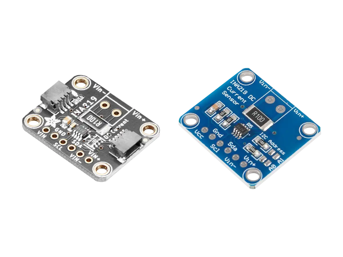
Adafruit also has a breakout board (PID 1164) for the INA169 current sensor shown in the figure below. This module measures DC current directly through an on-board 0.1Ω shunt resistor and also has an on-board 10kΩ load resistor proportional analog voltage output that you can plug into your microcontroller analog ADC pins.
Specs
| Feature | Description |
|---|---|
| Module Info | |
| INA169 IC Info | INA169 High-Side Measurement Current Shunt Monitor from Texas Instruments (TI) |
| Interface |
|
| Shunt Resistor (RS) | RS = 0.1Ω, 1% tolerance, 2W continuous current sense resistor that you can measure from 0.5A up to +5A continuous. |
| Load Resistor (RL) | The output is a current that is drawn through the on-board 10kΩ load resistor so that the output voltage is 1V per Amp. |
| Response Time |
|
| Operating Voltage | +2.7V to +60V DC. Power supply can be common or independent of load supply. |
| Operating Temperature | -40°C to +85°C |
Board Layout
The Adafruit INA169 board layout is shown in the figure below. This board comes with a 5-pin header, so you can easily attach this sensor to a breadboard, as well as a 3.5mm terminal plug so you can easily attach and detach your load.
| Pin Name | Function |
|---|---|
| VIN+ & VIN- |
Positive and negative input voltage.
Range: +2.7V to +60V DC with input current between 0.5A to 5A continuous |
| VCC |
Voltage supply for the INA169 IC
Range: +2.7V to +60V DC |
| VOUT |
Output analog voltage 1V/A
Voltage range limited by the lesser of IC power supply voltage VCC and VIN+. |
| GND | Common Ground |
Conclusion
The INA169 IC was covered along with two different breakout modules from SparkFun and Adafruit. A summary of the common features and differences between these two modules are listed below.
- Both modules come with external circuitry, onboard shunt and load resistors, and pin through holes.
- Both modules use precision 1% shunt resistors, with the SparkFun module having a larger resistance of 10Ω that can measure lower currents (from 3.5mA to 35mA continuous) and Adafruit having a smaller resistance of 0.1Ω that can measure higher currents (from 0.5A to 5A continuous).
- Both modules have the same 10kΩ load resistor that provides the same bandwidth and settling time, but the large difference in shunt resistances gives vary different output sensitivities: the SparkFun output is 0.1V per milliamp, whereas Adafruit's output is 1V per Amp.
- Both modules also include PTHPin Through Holes for replacing the load resistance to change the output voltage range and resolution.
Related Content


Products

Created:
12Apr2023 21:46:48 UTC
2023-04-12T21:46:48Z
Updated:
07May2024 23:46:11 UTC
2024-05-07T23:46:11Z
The INA169 High-Side DC Current Shunt Sensor modules output an analog voltage proportional to the input current that goes through a shunt resistor.
- SparkFun and Generic Modules (3.5mA to 35mA)
- Adafruit and Generic Modules (0.5A to 5A)
(0) Comments
Sign in to leave a comment
Sign In