INA282 Current Sensor
Updated: 22Aug2024 09:55:13 UTC 2024-08-22T09:55:13Z
Rating: (0 reviewsThis article has not been rated yet)
The INA282 High/Low Side Bidirectional Current Shunt Sensor ICIntegrated Circuit from Texas Instruments (TI) measures input current that goes through an external shunt resistor (RS) and outputs a proportional analog voltage with a gain of 50 V/V.
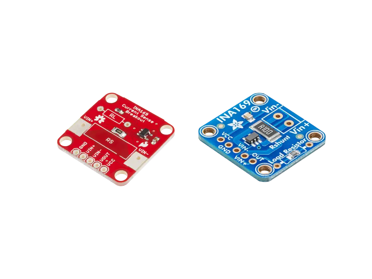
Breakout board modules for the INA282 IC are available with external circuitry and pin through holes to make the chip easy to interface to. This hardware overview of the INA169 IC and Module covers the board layout, pinout, specs, and operation.
INA169 vs INA282
There are several differences between the INA282 and INA169 provided in the table below. The main differences are the INA282 has either High/Low side current sensing, can measure bidirectional currents, a wider input voltage range, and has a voltage output with a preset gain instead of a current output. On the other hand, INA282 has a narrower supply voltage range and consumes more power than the INA169.
| Feature | INA169 | INA282 |
|---|---|---|
| High/Low Side Sensing |
High | High/Low |
| Current Direction | Unipolar | Bidirectional |
| Common-Mode Input Range |
+2.7V to +60V | -14V to +80V |
| CMRRCommon-Mode Rejection Ratio |
|
|
| Gain | Single Resistor Gain Set |
Fixed 50V/V Gain Set |
| Supply Range | +2.7V to +60V DC | +2.7V to +18V DC |
| Quiescent Current |
|
|
INA282 IC
Overview
The INA282 IC comes in two different SMDSurface Mount Device packages: a SOICSmall Outline Integrated Circuit-8 with a size of 4.90mm x 3.91mm (LxW, excluding pin length) or a smaller VSSOPVery-Thin Shrink Small-Outline Package. Also referred to MSOP (Micro Small-Outline Package)-8 with a size of 3.00mm x 3.00mm (LxW, excluding pin length).
The INA282 is part of the INA28x series that also includes the INA283, INA284, INA285, and INA286 ICs with the same 8-pin configuration and chip packages (SOIC, VSSOP) but different gains shown in the table below.
| IC | Gain |
|---|---|
| INA282 | 50 V/V |
| INA286 | 100 V/V |
| INA283 | 200 V/V |
| INA284 | 500 V/V |
| INA285 | 1000 V/V |
Pin Descriptions
| Pin | Name | Function |
|---|---|---|
| 1 | -IN | Analog Input. Connect this pin to load side of shunt resistor. |
| 2 | GND | Common Ground |
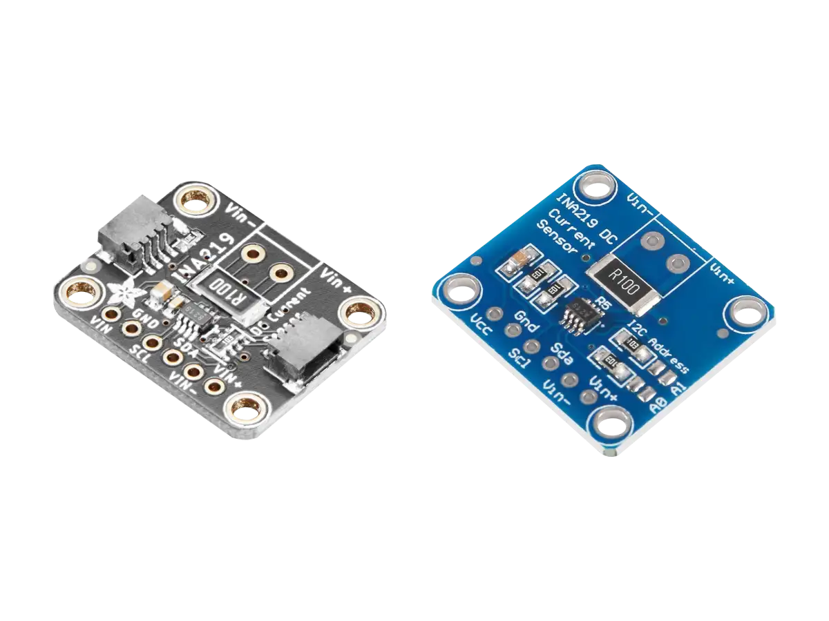
| 3 | REF2 | Analog input reference voltage, 0V to V+. (See INA219 IC Operation Section) |
| 4 | NC | This pin is not internally connected. Either float or connect this pin to GND. |
| 5 | OUT | Analog output voltage |
| 6 | V+ | Power supply, 2.7V to 18V DC |
| 7 | REF1 | Analog Input. Reference voltage, 0V to V+. (See INA219 IC Operation Section) |
| 8 | +IN | Analog Input. Connect this pin to supply side of shunt resistor. |
Operation
The INA282 IC measures input current (IS) that goes through an external shunt resistor (RS) and outputs a proportional analog voltage (OUT) with a gain of 50 V/V. The gain is how much the shunt resistor voltage is amplified.
The INA282 IC power supply V+ has a range of (+2.7V to +18V) and is independent of the load power supply (-14V to +80V). A power supply bypass capacitor is required for stability (typically 0.1μF).
The load current IS is drawn from load power supply through the shunt resistor RS. The voltage drop across shunt resistor is first fed into an input stage amplifier, then to a zero-drift amplifier that shifts the output voltage (OUT) around a reference voltage (REF1 and REF2 pins).
The reference pins, REF1 and REF2, are used to set the zero point output to (REF1 + REF2)/2. The REF1 and REF2 pins cannot be connected to any voltage source lower than GND or higher than V+ and the reference voltage (REF1 + REF2)/2 must be 9V or less. There are three reference voltages modes used that are commonly used.
- Ground Referenced Output:
- (REF1=REF2=GND) If REF1 and REF2 are both connected to ground, then the INA282 will be in unidirectional operation where 0V differential across the shunt resistor will produce a 0V output. The input current flows from VIN+ to VIN-.
- V+ Referenced Output:
- (REF1=REF2=V+) The V+ referenced output can be used for unidirectional reversed input currents that flows from VIN- to VIN+.
- Bidirectional Operation:
- (REF1=V+ & REF2=GND) Bidirectional operation can be configured by connecting REF1 to V+ (or some other voltage) and REF2 to ground, where the output voltage moves up/down from the reference voltage REF1 (within the supply rails) for positive/negative currents.
Reference pin connection options are provided in section 7.4.1 of the INA282 Datasheet (PDF).
Specs
| Feature | Description |
|---|---|
| IC Info | INA282 High/Low Side Bidirectional Current Shunt Monitor from Texas Instruments (TI) |
| Input Voltage |
|
| Output Voltage | VOUT = (50 V/V)·IS·RS |
| Gain |
|
| Offset Voltage | ±20μV (typical), ±70μV (max) |
| Bandwidth | 10kHz (typical) |
| Common-Mode Rejection Ratio (CMMR) |
|
| Operating Voltage | +2.7V to +18V DC. Power supply can be common or independent of load supply. |
| Quiescent (Sleep) Current |
600μA (typical), 900μA (max) |
| Operating Temperature | -40°C to +125°C |
| Package | SOIC-8 or VSSOP-8 |
| IC Size (LxWxH) |
|
INA282 Module
Overview
Breakout boards for the INA282 IC are available with external circuitry and pin through holes to make it easy to interface to. The module shown below has a simple board layout with only three components: the INA282 IC, power supply bypass capacitor, and a 0.1Ω 1% tolerance shunt resistor.
Board Layout
The INA282 module board layout is shown in the figure below. This board comes 6-pin through holes to solder on a 6-pin male header to attach this sensor to a breadboard. On the other end of the board are 2 input holes to solder a terminal plug to easily connect and disconnect your load.
Conclusion
The INA282 measures current by amplifying the voltage drop across a shunt resistor so it can be read by an ADC. The INA282 has some advantages over the INA169. The INA282 has either High/Low side current sensing, can measure bidirectional currents, a wider input voltage range, and has a voltage output with a preset gain instead of a current output.
Breakout board modules for the INA282 IC are available with external circuitry and pin through holes to make the INA282 IC easier to interface to. An example of a common INA282 module was provided with a simple board layout. The link in the products section below has a list of sellers that offer this module.
Resources
| Figure | Title | Description | Links |
|---|---|---|---|
|
|
INA282 Current Sensor | Article by Wolfgang Ewald on the INA282 with measurements using an Arduino Uno | Wolles-Elektronikkiste.de |
|
|
INA282 Current Shunt Monitor with Arduino | YouTube video by Gadget Reboot with measurements using an Arduino Uno | YouTube.com |
Related Content


Products

Created:
03Jun2024 06:39:11 UTC
2024-06-03T06:39:11Z
Updated:
03Jun2024 07:09:09 UTC
2024-06-03T07:09:09Z
The INA282 High-Side or Low-Side Bidirectional DC Current Shunt Sensor modules output an analog voltage proportional to the input current that goes through a shunt resistor.
(1) Comments
Sign in to leave a comment
Sign In
this is amazing ! thank you for the information