Measure Low DC Current with an INA169 and RPi Pico
Updated: 05Aug2024 06:59:08 UTC 2024-08-05T06:59:08Z
Rating: (0 reviewsThis article has not been rated yet)
This tutorial covers how to use the INA169 current sensor module to measure low current in milliamps with the Raspberry Pi (RPi) Pico microcontroller board. The output of the INA169 module is an analog voltage that can be read with the Analog-to-Digital Converter (ADC) of the Pico.
SparkFun has a breakout board for the INA169 IC with external circuitry, onboard shunt and load resistors, and pin through holes to make it easy to interface to. Generic boards with the same board layout and components are also available. The SparkFun and generic boards come with a high shunt resistance of 10Ω and output load resistance of 10kΩ that provides a low current sense range of 2.5mA to 23.6mA, but these resistances can be easily modified to allow higher input current. The current resolution can also be modified by changing the Pico ADC range or using an external ADC with a higher resolution.
INA169 Module
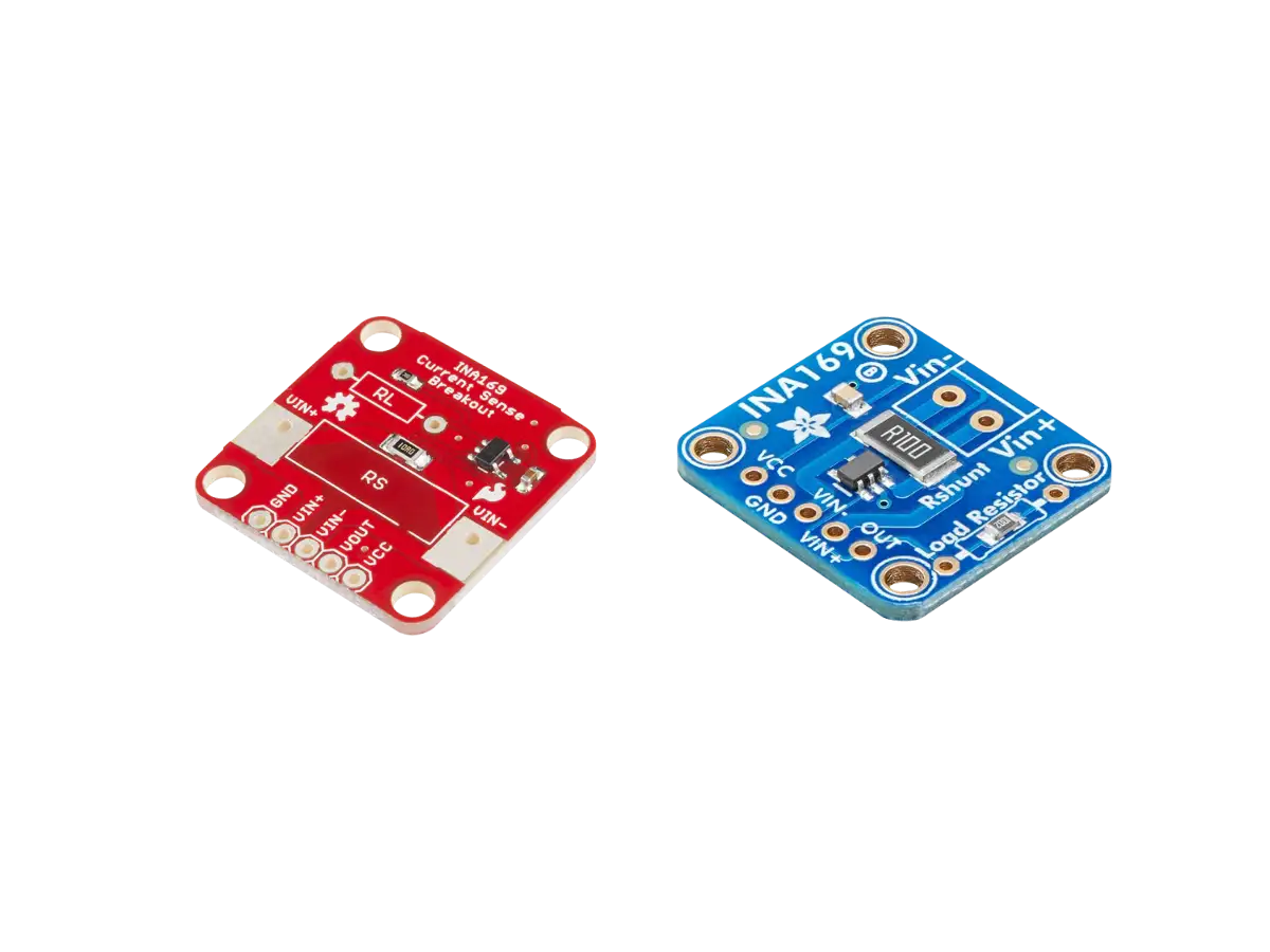
SparkFun has a breakout board (SEN-12040) for the INA169 current sensor shown in the figure below. For this board they've selected a shunt resistance (RS) of 10Ω with a current sense range of 2.5mA to 23.6mA and a load resistance (RL) of 10kΩ. A hookup guide for this board is available on their website.
| Feature | Description |
|---|---|
| IC Info | INA169 High-Side Measurement Current Shunt Monitor by Burr-Brown (BB) from Texas Instruments (TI) |
| Interface |
|
| Shunt Resistor | RS = 10Ω, 1% tolerance |
| Load Resistor | RL = 10kΩ |
| Response Time |
|
| Operating Voltage | +2.7V to +60V DC. Power supply can be common or independent of load supply. |
| Operating Temperature | -40°C to +85°C |
| Docs |
The SparkFun INA169 board layout is given below. PTHPin Through Holes are used for powering the board VCC and GND, the voltage across the shunt resistor VIN+ and VIN-, and the output VOUT. PTHs for RS and RL are also included to allow them to be replaced or modified (adding a resistor in parallel) with different values. A bypass capacitor of 0.1μF is included to reduce noise from the power supply to the IC.
| Pin Name | Function |
|---|---|
| VIN+ & VIN- |
Positive and negative input voltage.
Range: +2.7V to +60V DC |
| VCC |
Voltage supply for the INA169 IC
+2.7V to +60V DC |
| VOUT |
Output analog voltage 0.1V per milliamp
Voltage range limited by the lesser of the IC power supply voltage VCC and VIN+. |
| GND | Common Ground |
The load current IS measured by the module is drawn from load power supply through shunt resistor RS. The output load resistor RL converts the output current to a voltage VO at the VOUT pin. This output voltage VO is given in the equation below, where the constant 1/1kΩ (1000μA/V) is the transconductance of the INA169 IC.
The shunt voltage VIN = (VIN+) - (VIN-) and power supply voltage VCC limits the maximum possible output voltage swing. The maximum output voltage compliance (VOUTMAX) from the INA169 Datasheet is given below as the minimum of VCC - 0.7V - VIN and (VIN-) - 0.5V, whichever is lower.
The shunt current IS can be computed from the output voltage by the equation below.
RPi Pico Hookup
To power the INA169 module, connect the Pico 3.3V output pin to the INA169 VCC and the Pico GND pin to the INA169 GND. To read the output voltage level of the INA169 module, you need to connect the INA169 VOUT pin to one of the Pico's analog inputs, such as ADC0.
The external load in this example is a 330Ω resistor that is powered by the Pico from the 3.3V output pin. This will
provide a current through the load resistor of 3.3V/(330Ω + 10Ω) ≈ 9.7mA. You can
pick a different load resistor value if you want as long as the current is within the range of
2.5mA to 23.6mA (the Pico's 3.3V rail can provide up to 300mA of current). The load resistor
can be in the range of
(3.3V/23.6mA) - 10Ω ≈ 130Ω
to
(3.3V/2.5mA) - 10Ω ≈ 1.31kΩ.
The current needs to be measured on the high-side, so the 3.3V Pico pin is
connected directly to the INA169 V+ pin and the V- pin is connected to the load resistor and then to ground.
RPi Pico MicroPython Code
The Pico MicroPython code provided below reads the ADC0 pin at a sampling interval of a half a second. It assumes the ADC is using a 3.3V voltage reference (ref_voltage) and converts the ADC counts from 0 and 65535 to 0V and 3.3V. The voltage is converted to current in milliamps and printed to the serial monitor. The USB port on the Pico board is connected to a computer to transfer the data serially and display the results on the computer console.
The output of measuring the current from a 3.3V source through a 10Ω shunt and 330Ω load resistor is provided below.
Input Current Range
The INA169 output error increases once the voltage across RS dips below about 25mV as shown in the plot below from the INA169 datasheet. This sets a lower bound for the input current of 25mV/10Ω = 2.5mA.
The upper bound of the input current is determined by the maximum output voltage (VOUTMAX) that depends on both the shunt voltage VIN = (VIN+) - (VIN-) and power supply voltage VCC.
There are two conditions here based on the relationship between VCC and VIN+:
- If VIN+ ≥ VCC - 0.2V, then the max input current is IS(max) = (VCC - 0.7V)/(110Ω).
- If VIN+ < VCC - 0.2V, then the max input current is even lower with IS(max) = ((VIN+) - 0.5V)/(110Ω).
For this tutorial setup, VCC = VIN+ = 3.3V, so the maximum input current is IS(max)= (3.3V - 0.7V)/(110Ω) = 23.6mA.
In addition to choosing VCC and VIN+, the max input current range depends the value of the shunt resistor (RS). The default shunt resistance on the SparkFun board is 10Ω, but can be modified to allow lower/higher input current. The table below shows how the current sense range changes with different RS values. The power rating of the resistor also needs to be considered to ensure it can handle the current range.
| RS | Current Sense Range |
|---|---|
| 10Ω | 2.5mA - 23.6mA |
| 1Ω | 25mA - 236mA |
| 0.1Ω | 250mA - 2.36A |
There are pin through holes on the board to solder a parallel resistor across RS in order to reduce the overall shunt resistance. For example, a 1Ω parallel resistor gives an effective shunt resistance of 0.9Ω, which changes the input current range to 25mA - 236mA. In order to increase the shunt resistance to measure lower input current than 2.5mA, the 10Ω SMDSurface Mount Device resistor must be desoldered and replaced with a different resistor lower than 10Ω.
Another way of changing the input current range is to modify the 10kΩ load resistor (RL) to adjust the output voltage swing. There are pin through holes on the board to solder a parallel resistor across RL in order to reduce the overall load resistance. For example, if you inserted a parallel resistor of 1kΩ, then the effective load resistance lowers to RL = (10kΩ·1kΩ)/(10kΩ + 1kΩ) ≈ 0.91kΩ.
Modifying the load resistor RL changes the output voltage swing, but it must be below the maximum output voltage compliance (VOUTMAX) from the INA169 Datasheet.
Solving the inequality for the shunt current IS gives the maximum input current in terms of VCC and RL.
For the default RL = 10kΩ using VCC = 3.3V, the maximum input current is IS ≤ 23.6mA. If RL is lowered to 1kΩ, then the maximum input current is increased to IS ≤ 130mA. However, lowering RL to 1kΩ also decreases the output voltage swing from 2.36V to 1.30V max, so you will lose some resolution (from 8μA to 80μA).
Modifying the load Resistor RL instead of shunt resistor RS is a more convenient way of changing the input current range because you can use resistors with higher values which are easier to find and less expensive.
Resolution
The resolution of the SparkFun INA169 Module is 100mV/mA. The Pico 12-Bit ADC has a resolution of 3.3V/212 ≈ 0.8mV, which corresponds to about 8μA of current resolution. This is usually sufficient for most applications, but if the current range is increased by modifying RS, then the current resolution will decrease. For example, an RS = 0.1Ω with a current sense range of 250mA - 2.36A gives an INA169 resolution of 2.36V/2.36A = 1V/A that corresponds to about 0.8mA of current resolution using the Pico ADC. If you need to improve this resolution, there are a couple of ways to do this.
- Reduce the Pico ADC range closer to the INA169 2.36V max output using a reference voltage.
- Use an external ADC module with a higher resolution, such as the ADS1115 16-Bit ADC.
Using an ADS1115 ADC module has several advantages.
- Higher bit resolution
- Built-in voltage reference (no need for calibration)
- Programmable gain to change the ADC input voltage range and increase resolution
- Up to 4 single-channel inputs or two differential inputs
- Can be used with other devices with I2C, such as a different microcontroller, SBC, or USB Serial Adapter.
- Wider input range based on the ADC supply range from 2.0V to 5.5V (a bidirectional Logic Level Converter for I2C may be needed when using a 3.3V microcontroller with the ADC supplied by 5V),
- Low power consumption of 150µA in continuous mode and can be put into sleep mode between measurements with low current consumption of 0.5μA.
Conclusion
This tutorial covered how to use the INA169 current sensor module to measure low current in milliamps with the RPi Pico. The input current range and resolution of the INA169 can by changed with some modifications.
The input current is limited to the range of 2.5mA to 23.6mA with the default 10Ω shunt resistor (RS) and 10kΩ load resistor (RL) on the SparkFun INA169 module, but by adding a resistor in parallel to either the shunt or load resistors allows for higher input current.
The resolution can be improved by either reducing the Pico ADC range closer to the INA169 2.36V max output using a reference voltage or you can use an external ADC module with a higher resolution.
The precision and accuracy of measurements can be improved by calibrating the Pico ADC, using an external precision voltage reference (see Measuring DC Voltage with an RPi Pico for more details), or by using an external ADC such as the ADS1115 with higher resolution and a built-in voltage reference.
Related Content


Products

Created:
12Apr2023 21:46:48 UTC
2023-04-12T21:46:48Z
Updated:
07May2024 23:46:11 UTC
2024-05-07T23:46:11Z
The INA169 High-Side DC Current Shunt Sensor modules output an analog voltage proportional to the input current that goes through a shunt resistor.
- SparkFun and Generic Modules (3.5mA to 35mA)
- Adafruit and Generic Modules (0.5A to 5A)

Created:
27Jul2023 23:50:32 UTC
2023-07-27T23:50:32Z
Updated:
04Sep2024 00:31:23 UTC
2024-09-04T00:31:23Z
- Processor:
- 32-bit 133MHz Dual-Core ARMAdvanced Reduced Instruction Set Computer (RISC) Machines Cortex-M0+
- Memory:
- 2MB QSPIQuad Serial Peripheral Interface (QSPI) is a serial communication interface designed for talking to flash chips by using 4 data lines. Flash and 264KB SRAMStatic Random Access Memory
- Interface:
- 1x Micro-B USB, Up to 30x Digital I/OInput/Output with PWMPulse-Width Modulation, 4x Analog Inputs 12-bit ADCAnalog-to-Digital Converter (ADC, A/D, or A-to-D), 2x UARTUniversal Asynchronous Receiver-Transmitter, 2x I2CInter-Integrated Circuit. Also referred to as IIC or I2C., 2x SPISerial Peripheral Interface, and PIOProgrammable Input/Output (PIO) can be programmed to process data transmission, such as a non-standard serial interface, without using resources from the CPU.
- Boards:
- RPiRaspberry Pi Pico, Pico H, Pico W, and Pico WH

Created:
11Dec2022 23:50:41 UTC
2022-12-11T23:50:41Z
Updated:
04Sep2024 22:33:49 UTC
2024-09-04T22:33:49Z
- Processor:
- 32-bit 133MHz Dual-Core ARMAdvanced Reduced Instruction Set Computer (RISC) Machines Cortex-M0+
- Memory:
- 2MB QSPIQuad Serial Peripheral Interface (QSPI) is a serial communication interface designed for talking to flash chips by using 4 data lines. Flash and 264KB SRAMStatic Random Access Memory
- Interface:
- Up to 30x Digital I/OInput/Output with PWMPulse-Width Modulation, 4 channel 12-bit 500kbs ADCAnalog-to-Digital Converter (ADC, A/D, or A-to-D), USB 1.1 Host and Device Full/Low speed, and UARTUniversal Asynchronous Receiver-Transmitter/I2CInter-Integrated Circuit. Also referred to as IIC or I2C./SPISerial Peripheral Interface/PIOProgrammable Input/Output (PIO) can be programmed to process data transmission, such as a non-standard serial interface, without using resources from the CPU.
- Boards:
-
- RPiRaspberry Pi Pico, Pico H, Pico W, Pico WH
- Adafruit QT Py, ItsyBitsy, Feather
- SparkFun Pro Micro, Thing Plus
- Pimoroni Tiny 2040, Pico LiPo
- Seeed Studio XIAO
- Waveshare RP2040-Zero, RP2040-Plus

Created:
26May2024 21:29:57 UTC
2024-05-26T21:29:57Z
Updated:
27May2024 03:59:16 UTC
2024-05-27T03:59:16Z
- LM4040 Modules
- AD584 Modules

Created:
14Aug2022 21:16:24 UTC
2022-08-14T21:16:24Z
Updated:
14May2024 05:51:53 UTC
2024-05-14T05:51:53Z
- 10-Bit, 12-Bit, 16-Bit, and 24-Bit ADCs
- ICs and Modules
(0) Comments
Sign in to leave a comment
Sign In