Current Sensors
Updated: 23Aug2024 01:01:17 UTC 2024-08-23T01:01:17Z
Rating: (0 reviewsThis article has not been rated yet)
The sensors discussed here measure electrical current and provide an output, either analog voltage or digital, that corresponds to the current being measured.
In general, there are two main ways to measure current. The first method is directing the current through a small shunt resistor and measuring the differential voltage across it that results from the current flow. The second method is measuring the magnetic field that results from current, as done with Hall Effect Current Sensors and Solid/Split Core Current Transformers (CTCurrent Transformer).
This overview will be cover Shunt Resistor Current Sensors, Hall Effect Current Sensors, Solid Core CTs, Split Core CTs, and the Coulomb Counter.
Selection Criteria
Important distinctions need to be made when selecting a current sensor. The following are essential criteria on how the current sensor will interact and operate in the desired environment.
- ACAlternating Current or DCDirect Current:
- If the input current alternates between positive and negative then an AC current sensor is required. A DC current sensor can only measure positive unipolar current, but the sensor may allow the signal to vary over time between zero and positive values such as a square wave if it is within the specs bandwidth and response time. Some current sensors can measure both AC and DC.
- Invasive or Non-Invasive:
- If the current sensor requires the circuit to be broken and connected in-line it is considered invasive. If it is a non-contact sensor, such as being near or clamped around the wire being measured, it is considered non-invasive. There are trade-offs to be made between the two types of sensors. Usually, the invasive sensors are more accurate than non-invasive sensors, but breaking the circuit may be difficult or impractical depending on the application.
- Current Measuring Range:
- This is the minimum and maximum current the sensor is capable of measuring. Exceeding these limits may render inaccurate results or damage the sensor and devices connected to it (if there is not isolation or protection circuitry).
- Input Current Measuring Range:
- This is the minimum and maximum current the sensor is capable of measuring.
- Isolation Voltage:
- The maximum voltage that the sensor can handle to protect itself and the devices connected to it.
- Supply Voltage (VCCVoltage Collector Collector (VCC) is the supply voltage at the collector of a transistor. The double subscript notation of repeating letters "CC" is used to denote a power supply voltage that is relative to ground. ):
- The voltage range required to operate the current sensor.
- Frequency Range:
- This is what input frequencies that the sensor can respond to and is often referred to as bandwidth in the sensor specs. This is not just for AC current sensors, but also for DC current sensors that can measure signals that vary over time between zero and positive values such turning on and off.
- Response Time:
- The time lapsed between an input and the corresponding output signal. This determines how fast the current signal can be sampled and may be specified as the settling time of the sensor.
- Operating temperature:
- The minimum and maximum temperature in Celsius the sensor is designed to operate in. Exposure to temperatures outside of this range can damage the sensor.
- Accuracy, Precision, and Sensitivity:
- The term accuracy refers to how close the measured current value is to the true value. The accuracy of a current sensor can have dependencies such as temperature, the amount of input current/voltage, and/or the configuration of the sensor, whereas offset errors can be independent of the amount of input. Precision is the repeatability of the output due to noise or quantization. Sensitivity is the smallest amount of change that can be detected by a measurement: how much the output changes with changes to the input (e.g., mV/A).
Shunt Resistor Current Sensors
A common way to measure current is to convert it into a voltage by inserting a precision shunt resistor within the circuit in series with the load. The shunt resistor creates a voltage across it that is proportional to the current flow.
The shunt resistance is often very low, on the order of milliohms, so it does not steal voltage from the load and affect the current flow being measured. This means the voltage across the shunt resistor is also quite small, and often requires amplification before being read by an ADCAnalog-to-Digital Converter (ADC, A/D, or A-to-D).
There are two ways the shunt resistor can be placed in series with the load, called low-side sensing or high-side sensing. In low-side sensing, the shunt resistor (RS) is placed between the ground terminal of the power supply and the ground terminal of the load as shown in the figure below.
In high-side sensing, the shunt resistor is placed between the positive terminal of the power supply and the supply input of the load as shown in the figure below.
Low-side sensing is preferred for measuring current in applications with very high voltages/current or where the supply voltage may be prone to spikes or surges. One disadvantage of low-side sensing is its inability to detect ground faults (a short to ground) within the load. Another problem with low-side sensing is ground loop issues that can result in noise and interference, due to the shunt resistor placed between the load and ground where the load may not be at the exact same ground potential as the rest of the circuitry.
Two examples of shunt resistor current sensor ICIntegrated Circuits with an analog output are the INA169 and INA282. The INA169 only has high-side sensing and can only measure currents in one direction, whereas the INA282 has either high or low side sensing and can measure bidirectional currents.
The INA169 outputs an analog current that requires an external resistor to set the gain and convert it to an analog voltage output. The INA282 has an analog voltage output with a fixed gain of 50 V/V (there are other ICs in the INA28x series with higher gains). Both of these ICs and their breakout boards are covered in the next two sections.
INA169
The INA169 High-Side Unipolar Current Shunt Monitor IC from Texas Instruments converts a differential input voltage on an external shunt resistor (RS) to a current output that is converted back to a voltage with an external load resistor (RL) with any gain from 1 to over 100. The INA169 is designed to measure DC current and cannot measure AC current.
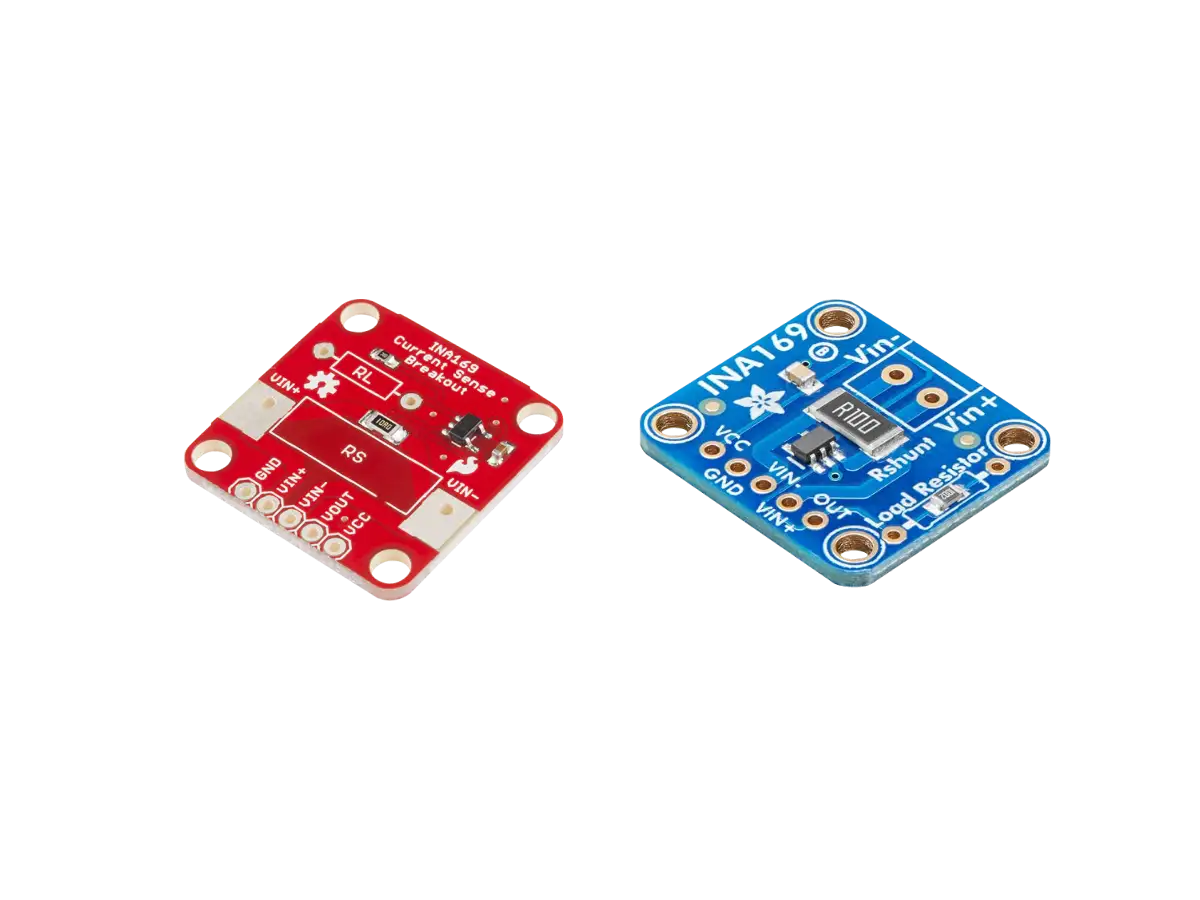
SparkFun has a breakout board (SEN-12040) for the INA169 current sensor shown in the figure below. For this board they've selected a shunt resistance (RS) of 10Ω with a current sense range of 3.5mA to 35mA and a load resistance (RL) of 10kΩ.
The SparkFun INA169 board layout is given below. PTHPin Through Holes are used for powering the board VCC and GND, the voltage across the shunt resistor VIN+ and VIN-, and the output VOUT. PTHs for RS and RL are also included to allow them to be replaced or modified (adding a resistor in parallel) with different values. A bypass capacitor of 0.1μF is included to reduce noise from the power supply to the IC.
SparkFun has a hookup guide and schematic available for their INA169 breakout board.
Adafruit also has a breakout board (PID 1164) for the INA169 current sensor by Burr-Brown (BB) from Texas Instruments (TI) shown in the figure below. This module measures DC current directly through an on-board 0.1Ω shunt resistor and also has an on-board 10kΩ load resistor proportional analog voltage output that you can plug into your microcontroller analog ADCAnalog-to-Digital Converter (ADC, A/D, or A-to-D) pins.
The Adafruit INA169 board layout is shown in the figure below. This board comes with a 5-pin header, so you can easily attach this sensor to a breadboard, as well as a 3.5mm terminal plug so you can easily attach and detach your load.
More details on both the SparkFun and Adafruit INA169 boards can be found in the articles below.
Created:
27Apr2023 19:38:46 UTC
2023-04-27T19:38:46Z
Updated:
24Aug2024 01:44:19 UTC
2024-08-24T01:44:19Z
Rating: (0 reviewsThis article has not been rated yet)
The INA169 High-Side DC Current Shunt Sensor IC outputs an analog voltage proportional to the current that goes through a shunt resistor. Both SparkFun and Adafruit have breakout boards for the INA169 IC with external circuitry and pin through holes to make it easy to interface to.

Created:
13Jun2024 10:09:20 UTC
2024-06-13T10:09:20Z
Updated:
05Aug2024 04:15:30 UTC
2024-08-05T04:15:30Z
Rating: (0 reviewsThis article has not been rated yet)
Measure low DC current in milliamps with the INA169 Module and Arduino Uno R3
- INA169 Current Sensor Module Pinout & Specs
- Arduino Uno R3 and INA169 Hookup
- Arduino Code and Output
- Input Current Range and Resolution

Created:
18Jul2024 02:08:13 UTC
2024-07-18T02:08:13Z
Updated:
05Aug2024 06:59:08 UTC
2024-08-05T06:59:08Z
Rating: (0 reviewsThis article has not been rated yet)
Measure low DC current in milliamps with the INA169 Module and RPi Pico
- INA169 Current Sensor Module Pinout & Specs
- RPi Pico and INA169 Hookup
- MicroPython Code and Output
- Input Current Range and Resolution
INA282
The INA282 High/Low Side Bidirectional Current Shunt Sensor ICIntegrated Circuit from Texas Instruments measures input current that goes through an external shunt resistor (RS) and outputs a proportional analog voltage (OUT) with a gain of 50 V/V.
Breakout boards for the INA282 IC are available with external circuitry and pin through holes to make it easier to interface to the IC. The module shown below has a simple board layout with only three components: the INA282 IC, power supply bypass capacitor, and a 0.1Ω 1% tolerance shunt resistor.
There are several differences between the INA282 and INA169 provided in the table below. The main differences are the INA282 has either High/Low current sensing, can measure bidirectional currents, a wider input voltage range, and has a voltage output with a preset gain instead of a current output. On the other hand, INA282 has a narrower supply voltage range and consumes more supply current than the INA169.
| Feature | INA169 | INA282 |
|---|---|---|
| High/Low Side Sensing |
High | High/Low |
| Current Direction | Unipolar | Bidirectional |
| Common-Mode Input Range |
+2.7V to +60V | -14V to +80V |
| CMRRCommon-Mode Rejection Ratio |
|
|
| Gain | Single Resistor Gain Set |
Fixed 50V/V Gain Set |
| Supply Range | +2.7V to +60V DC | +2.7V to +18V DC |
| Quiescent Current |
|
|
The INA282 is part of the INA28x series that also includes the INA283, INA284, INA285, and INA286 ICs with the same 8-pin configuration and chip packages (SOIC, VSSOP) but different gains shown in the table below.
| IC | Gain |
|---|---|
| INA282 | 50 V/V |
| INA286 | 100 V/V |
| INA283 | 200 V/V |
| INA284 | 500 V/V |
| INA285 | 1000 V/V |
More details on the INA282 IC and Module can be found in the INA282 Current Sensor article below.

Created:
21Aug2024 22:06:43 UTC
2024-08-21T22:06:43Z
Updated:
22Aug2024 09:55:13 UTC
2024-08-22T09:55:13Z
Rating:
(0 reviewsThis article has not been rated yet)
The INA282 is a High/Low Side Bidirectional Current Shunt Sensor outputs an analog voltage proportional to the current that goes through a shunt resistor. Breakout boards for the INA282 IC are available with external circuitry and pin through holes to make it easy to interface to.
Hall Effect Current Sensors
The Hall Effect is a phenomenon in which a potential difference (the Hall voltage) is produced in a conductor (or semiconductor) when it is carrying a current perpendicular to a magnetic field. This effect was discovered by the American physicist Edwin Herbert Hall in 1879.
The Hall Effect can be used to measure current. When current (I) flows through a conductor, a magnetic field (B) is created. If a biased Hall Effect element is placed near the current conductor, the magnetic field produces a small Hall voltage (VH) across the element. This Hall voltage is amplified to provide a voltage output that can be read by an ADC or voltmeter. Since there is a linear relationship between the output voltage and the current measured, the value of the current can be computed.
Hall Effect current sensors are designed for higher current in Amps. For lower currents the Hall effect loses strength as the current drops and increasing the sensing length would increase resistance and thus heat generated within the part.
The advantage of using a Hall Effect current sensor is that the circuit being sensed and the circuit reading the sensor are electrically isolated, since they are not physically connected. This means you can use a low power device, such as a microcontroller or SBC, to measure the current (DC or AC) going through a high power device.
Three popular Hall Effect current sensor ICs in modules that you will see on the market are the ACS712, ACS723LCC and ACS758 series from AllegroTM. These ICs have different input current ranges and sensitivities (S) with an an output that is offset by VCC/2. The input current (I) can be omputed from the output voltage (VOUT) by the following equation.
I = (VCC/2 - VOUT)/S
A comparison of the ACS712, ACS723LCC, and ACS758 IC specs is provided in the table below.
| Parameter | ACS712 | ACS723LLC | ACS758 |
|---|---|---|---|
| Current Range & Sensitivity |
|
|
|
| Current Resolution |
|
|
|
| Path Resistance | 1.2mΩ | 0.6mΩ | 0.1mΩ |
| Isolation Voltage |
Basic: 354Vpk or VDC
Reinforced 184Vpk or VDC |
Basic: 420Vpk or VDC / 297Vrms |
Basic: 990Vpk or VDC / 700Vrms
Reinforced: 636Vpk or VDC / 450Vrms |
| Bandwidth | 80kHz (typical) | 80kHz / 20kHz Pin-Selectable | 120kHz (typical) |
| Response Time | 3.5µs (typical) |
Pin-selectable response time:
|
4µs (typical) |
| Voltage Supply | 4.5V to 5.5V single supply |
4.5V to 5.5V single supply |
3V to 5.5V single supply |
| Accuracy | ±1.5% at TA = 25°C |
|
|
| Package | SOIC8 | SOIC8 | 5-Pin CB PFF Leadform |
The ACS723LL and ACS712 perform better at lower currents down to about 100mA. The ACS758 has the highest available input current range, can measure higher frequencies, the lowest path resistance, highest isolation voltage, and can accept down to 3V for the voltage supply (making it compatible with 3.3V microcontrollers and SBCs). The ACS758 is also more expensive, over double the price of the ACS712.
The ACS devices for different current ranges mostly only differ in the internal amplification stage. The sensitivity of these ICs can be increased by adding external OpAmps to the output, but you will also be amplifying the noise and offset errors by the same factor.
The zero input current output voltage VCC/2 output voltage would also present a challenge for adding external amplification circuitry. These chips are designed for measuring amps and there are better alternatives for measuring low current in the milliamps or even microamp range, such as the INA169 and INA219 shunt current sensors.
The ICs have a basic isolation from 354Vpk for the ACS712 to 900Vpk for the ACS758, making them able to handle higher voltages, such as mains 120V/220V RMS. However, many of PCB boards the chip is implemented in are questionable when used for currents higher than 5A and high mains 120V/220V RMS voltages. The input traces need to be thick enough to handle large currents (much wider pads compared to the low current output traces in the PCB). For high mains voltages, there should be about 4mm clearance/creepage between the high voltage input and the local ground plane/traces or the 5V VCC traces (i.e., wherever there is a large potential difference). If you are working with mains voltages, the larger ACS758 is a better option or use a safer alternative such as a current transformer (CT).
ACS712
The ACS712 Hall Effect based linear current sensor ICIntegrated Circuit from AllegroTM measures AC or DC current and provides a proportional output voltage. There are 3 versions of this IC listed below with different max input current ratings and sensitivities.
| Part Number | Current Rating |
Sensitivity (typical) |
|---|---|---|
| ACS712ELCTR-05B-T | ±5A | 185mV/A |
| ACS712ELCTR-20A-T | ±20A | 100mV/A |
| ACS712ELCTR-30A-T | ±30A | 66mV/A |
The most common module for the ACS712 IC is shown below. There are 3 different modules listed as 5A, 20A, and 30A that look identical in size and layout to the one shown below, but can be distinguished by the different markings ACS712 IC indicating what chip is used.
The board layout is shown below that consists of an input screw terminal block (IP+ and IP-) and 3-pin header for powering the IC (VCC and GND) with +5V DC and the analog output (OUT). The board also has a LED power indicator that lights up when power is applied across VCC and GND.
CZH-LABS also makes a different type ACS712 module shown below that has an onboard LM317 regulator with supported circuitry for a wider VCC range that can accept either +5V or larger voltages from +8V to +35V. This board also jumper pins if you want apply a 100nF bypass capacitor to the analog output to reduce noise.
ACS723
The ACS723 Hall Effect based linear current sensor IC from AllegroTM measures AC or DC current and provides a proportional output voltage. Compared to the ACS712, the ACS723 has more options with different versions of the chip over a greater range of input current, a lower path resistance of 0.6mΩ, higher isolation voltage (Basic 420Vpk or VDC / 297Vrms), an 80kHz / 20kHz Pin-Selectable bandwidth, and a higher sensitivity. However, the ACS723 has a lower accuracy than the ACS712.
There are 5 bidirectional versions of the ACS723 IC listed below with different max input current ratings and sensitivities.
| Part Number | Current Rating |
Sensitivity (typical) |
|---|---|---|
| ACS723LLCTR-05AB-T | ±5A | 400mV/A |
| ACS723LLCTR-10AB | ±10A | 200mV/A |
| ACS723LLCTR-20AB-T | ±20A | 100mV/A |
| ACS723LLCTR-40AB | ±40A | 50mV/A |
| ACS723LLCTR-50AB | ±50A | 40mV/A |
SparkFun has two breakout boards for the ACS723LLCTR-05AB-T IC version, one for moderate current (SEN-13679) and the other for low current (SEN-14544).
The moderate current module can measure current up to 5A with a base sensitivity of 400mV/A. The lowest current will be limited by either the current resolution of the IC (90mA at 80kHz, 45mA at 20kHz) or by the noise and the resolution of the ADC reading the output.
The low current module (SEN-14544) is an amplified breakout board with an adjustable sensitivity that is capable of sensing very small currents down to around 10mA and large currents up to 5A (usable readings on low current will be limited by noise and the resolution of the ADC reading the output).
The SparkFun ACS723 Low Current Sensor Breakout (SEN-14544) has two potentiometers on it marked Vref and GAIN.
The Vref potentiometer sets the baseline voltage output. It adjusts the voltage seen at Vo when there is no current flowing through the sensor (0mA). This allows the sensor to output negative current readings as well as positive.
The GAIN potentiometer sets the sensitivity of the device with a gain of 2.2 to 22 V/V. If the gain is set high, then a smaller current will cause the voltage output to increase more, giving you higher sensitivity and allowing you to sense smaller currents. However, with higher gain you will see more noise (spikes) on the output, so smaller currents will be harder to measure accurately. Also, if you are trying to measure larger currents with a high gain setting, your output will saturate or clip and reach the maximum 5V or 0V.
ACS758
The ACS758 Hall Effect based linear current sensor IC from Allegro™ measures AC or DC current and provides a proportional output voltage. Compared to the ACS712 and ACS723, the ACS758 has more options for greater input current with different versions of the chip, a lower path resistance of 0.1mΩ, higher isolation voltage (Basic 990Vpk or VDC / 700Vrms and Reinforced 636Vpk or VDC / 450Vrms), and a bandwidth of 120kHz, and a wider VCC supply range of 3.0V to 5.5V. However, the ACS758 has reduced sensitivity and accuracy compared to the ACS712 and ACS723.
There are 4 bidirectional versions of this IC listed below with different max input current ratings and sensitivities.
| Part Number | Current Rating |
Sensitivity (typical) |
|---|---|---|
| ACS758LCB-050B-PFF-T | ±50A | 40mV/A |
| ACS758LCB-100B-PFF-T | ±100A | 20mV/A |
| ACS758KCB-150B-PFF-T | ±150A | 13.3mV/A |
| ACS758ECB-200B-PFF-T | ±200A | 10mV/A |
The most common module for the ACS758 uses the ACS758LCB-050B-PFF-T version of the IC as shown in the figure below. The board size is 40mm x 20mm and usually comes with a separate 4-pin header that you can solder on the board.
The board layout is shown below that consists of an input PTHs where you can add screw terminal block and 4-pin header for powering the IC (VCC and GND) with +3V to +5V DC and the analog output (OUT). The board also has a LED power indicator that lights up when power is applied across VCC and GND.
There are two output pins called OU1 and OU2. The OU1 is from the output of the ACS758 chip via a 120Ω series resistor (an unbuffered output that should also work for 3V3 to connect to high impedance ADC inputs). The OU2 is connected to the output of an OpAmp (TI 2272) in voltage follower configuration to buffer ACS758 output for low impedance ADC inputs.
Other versions of the ACS758 IC with higher current ranges (±50A, ±100A, and ±150A) are available in the boards from CZH-LABS. These boards have an onboard LM317 regulator with supported circuitry for a wider VCC range that can accept either +5V or larger voltages from +8V to +35V. This board also jumper pins if you want apply a 100nF bypass capacitor to the analog output to reduce noise. The board size is 72.5mm x 47.35mm x 24mm (LxWxH).
Solid Core Current Transformer (CT) Sensors
Current Transformers (CT) are used to measure high current through a wire by stepping the current down to a lower level that can be measured by low power devices. They operate by magnetic induction on the CT secondary output windings from a changing magnetic field (B) produced by a current carrying conductor (I).
The input and output current transformation has a proportional relationship that is dependent on the number of turns (N) of the secondary conductor in the CT. The output of the CT is a current signal, which can be converted to a voltage signal using a burden resistor.
Solid Core CTs have a permanently closed core, so when used to measure the current in a wire it requires disconnecting the wire to get it through the hole of the CT.
ZMCT103C
The ZMCT103C is a Single Phase AC Current Transformer (CT) that has a ±5A range with 1000:1 turns ratio, high galvanic isolation, and a small size of 28mm x 12mm x 15mm (LxWxH). The output of this CT is a current signal, which needs to be converted to a voltage signal using a burden resistor.
The simplest version of a ZMCT103C module is shown below with just a 200Ω precision burden resistor across the transformer so that a voltage can be read from the two output pins.
An input of 5A into the transformer will produce 5mA through the resistor, giving a voltage output of (5mA)x(200Ω) = 1V. If an AC signal in the range ±5A is input into the transformer, then the output will be a positive and negative AC voltage in the range ±1V. If the output of this sensor is intended to be read by an ADC, some additional circuitry will be needed to shift the voltage into the positive range.
The board layout is shown below, with a small size of 18.3mm x 17mm and only two pins labeled G for Ground and S for the output Signal.
The ±5A ZMCT103C OpAmp module shown below also includes a series of OpAmps that shifts the negative AC voltage across the burden resistor into the positive range and amplifies/attenuates the signal for an ADC.
The required output voltage can be adjusted via the onboard trim potentiometer to change the amplification ratio and the amplification range 0-100 times, but the maximum voltage at the output terminal (OUT) will not exceed 1/2 VCC, where the power supply VCC can be anywhere from +5V to +30V DC.
Since the output voltage depends the potentiometer setting, this module needs to be calibrated with another meter that can measure the input current in order to determine the scale factor that converts the output voltage to the input current.
The layout of the board is shown below with a size of 38mm x 18.5mm x 21mm and a 4-Pin header. The VCC pin is to supply power to the OpAmp, OUT for the output, and two GND ground pins are internally connected together. This board also has an on-board power indicator LED that lights up when power is connected to VCC and GND.
TA12-100
The TA12-100 is a Single Phase AC Current Transformer (CT) that has a ±5A range with 1000:1 turns ratio, high galvanic isolation, and a small size of 17.2mm x 9.5mm x 20.4mm (LxWxH). The output of this CT is a current signal, which needs to be converted to a voltage signal using a burden resistor.
The most common TA12-100 CT module shown below has a 200Ω precision burden resistor across the transformer so that a voltage can be read from the two output pins.
An input of 5A into the transformer will produce 5mA through the resistor, giving a voltage output of (5mA)x(200Ω) = 1V. If an AC signal in the range ±5A is input into the transformer, then the output will be a positive and negative AC voltage in the range ±1V. If the output of this sensor is intended to be read by an ADC, some additional circuitry will be needed to shift the voltage into the positive range.
This module has a small size of 30mm x 24mm x 17mm. There is a 3-pin header labeled G, N, and S, where you can connect the signal line to S and ground to G, but the N pin is not connected. The board also includes a 4-pin JSTJapan Solderless Terminal connector, where only the two end pins are connected for signal and ground (the two middle pins are not connected).
Split Core Current Transformer (CT) Sensors
Split Core Current Transformers (CTs) are a type of non-intrusive sensor that have a "split" in the core that allows the CTs to open and be placed around an AC current carry wire without having to break/disconnect the wire in the circuit, which makes them both convenient to use and safer when working with higher currents.
Split Core CTs do not measure DC current, so you will need a different type of device for that. Some Split Core CTs have a built-in resistor that outputs an AC voltage and some do not that outputs an AC current. You will have to check the product page or datasheet to determine if the output is voltage or current.
The CTs examples mentioned below output an AC waveform, so if an ADC will be reading the output you will need some additional circuitry to shift the center up from zero volts to the positive range of your analog input. You should also have some kind of over-voltage protection if high current transients spikes can occur in the circuit being measured.
SCT-013
The SCT-013 Single Phase AC Split Core Current Transformer (CT) measures current through a wire and has a built-in resistor to output a proportional voltage with a standard 3.5mm audio plug. The AC frequency range of this device is 50Hz to 1kHz, making it useful for mains electricity monitoring.
The SCT-013 comes in 10 different versions, each with their own maximum input current rating, as shown in the table below. The output of SCT-013-000 is a current in the range of 0 to 50mA, where you can add your own burden resistor across the output terminals to produce an output voltage. The output of SCT-013-005 through SCT-013-100 is a voltage in the range of 0V to 1V. The higher current rating allows you to measure current over a wider range, but at a cost of lower sensitivity.
| Model | Input Current Rating |
Output |
|---|---|---|
| SCT-013-000 | 100A | 0mA to 50mA |
| SCT-013-005 | 5A | 0V to 1V |
| SCT-013-010 | 10A | 0V to 1V |
| SCT-013-015 | 15A | 0V to 1V |
| SCT-013-020 | 20A | 0V to 1V |
| SCT-013-025 | 25A | 0V to 1V |
| SCT-013-030 | 30A | 0V to 1V |
| SCT-013-050 | 50A | 0V to 1V |
| SCT-013-060 | 60A | 0V to 1V |
| SCT-013-100 | 100A | 0V to 1V |
PZCT-02
The PZCT-02 is another Single Phase AC Split Core Current Transformer (CT) shown below that measures current over a range of 0A to 100A through a wire and outputs a proportional current with a ratio of 1000:1.
If 1A current passes through the center hole it will induce a current of 1mA in the secondary. If you connect a 10 Ohm resistor across the secondary, then you would get 10mV across the resistor.
An AC 120V/220V/380V power supply can be applied, with frequency range of 50Hz to 60Hz, making it useful for mains electricity monitoring. The core hole diameter is 16mm.
Coulomb Counters
Coulomb counters can keep track of cumulative current use. They are capable of constantly monitoring the current your device is using, add it up, and will give you a pulse each time a given amount of amp-hours have been used. This is especially when you're trying to determine how much power is left in a battery.
LTC4150
The LTC4150 IC by Linear Technology measures battery depletion and charging for 1-cell or 2-cell Li-ionLithium-ion and 3-cell to6-cell NiCdThe nickel-cadmium (NiCd) battery is a type of rechargeable battery using nickel oxide hydroxide and metallic cadmium as electrodes. or NiMHThe nickel-metal hydride (NiMH) battery is a type of rechargeable battery. NiMH batteries can have two to three times the capacity of NiCd batteries of the same size. applications.
The device monitors current through an external sense resistor between the battery's positive terminal and the battery's load or charger. A voltage-to-frequency converter transforms the current sense voltage into a series of output pulses at the interrupt pin. These pulses correspond to a fixed quantity of charge flowing into or out of the battery. The LTC4150 also indicates charge polarity as the battery is depleted or charged.
SparkFun has a breakout board (BOB-12052) for the LTC4150 shown below. It uses a small 0.05Ω Sense Resistor for the LTC4150 to measure the voltage drop that is directly proportional to the current passing through the resistor.
The SparkFun board can handle power sources up to 8.5V with a maximum current of 1A and provides a resolution 5859 ticks per Ah. If you want more resolution (ticks per Ah) at a lower maximum current, or want more current (up to 1.6A) at less resolution, you can replace this resistor with a different value part. The PCB traces on the board are not designed to handle more than 1.6A continuously, and the JST connectors are not designed for more than 2A.
The board layout is shown below. You simply install this breakout out between your power source and your circuit, so all the current your circuit uses needs to pass through the Coulomb Counter to be measured.
On the right side of the board are headers labeled IN and OUT and a JST battery connector. You connect your battery or power supply to the IN header or JST battery connector (they are identical), and connect the OUT header to your application load.
On the left side of the board there is header with six pins where you connect your microcontroller to and include VIO (Voltage Input), INT (Interrupt), POL (Polarity), GND (Ground), CLR (Clear), and SHDN (Shutdown). The line above the names indicates an "active low" signal. The INT line is normally high, but will pulse low each time 0.614 coulombs passes through the device (which also happens to equal 0.1707mAh or 0.0001707Ah).
Keeping track of your battery's State Of Charge is done in software (i.e., the program of your microcontroller or computer software).
- First initialize a battery state variable to your battery's initial SOCState Of Charge in units of mAh or Ah. If you're starting with a fully charged battery, this will be the battery capacity in mAh or Ah.
- The device reading the Coulomb Counter listens for the tick (low) signals from the INT pin.
- Each time a tick is detected, check the direction of the signal on the polarity pin (POL), and add or subtract the per-tick mAh value (0.1707 mAh) to your battery-state variable accordingly. The polarity pin is Low when current flows from IN to OUT (discharging) and High when current flows from OUT to IN (charging).
If you record the time between ticks (t), you can also get the average current in Amps (Iavg) with Iavg = (0.614 C) / t.
Conclusion
The sensors discussed here measure electrical current with different benefits and usage. Selecting a current sensor depends on the current direction (AC/DC), how much accuracy is needed, the current measurement range, electrical isolation, and/or whether battery depletion/charging needs to be monitored.
- Shunt Resistor Current Sensors are the most accurate way to measure DC current, but have a lower input current range and do not provide electrical isolation.
- Hall Effect Current Sensors are less accurate, but can measure either AC or DC current and have a wider input current range.
- Solid/Split Core CTs are the least accurate used for large AC currents as a non-invasive and electrically isolated safe way to drop the current down to a lower level that can be measured by low power devices.
- Coulomb Counters can keep track of the cumulative DC current consumed in amp-hours and are useful in low voltage battery applications where the amount of battery depletion and charging needs to be monitored.


(0) Comments
Sign in to leave a comment
Sign In