Created:
11Apr2023 08:14:01 UTC
2023-04-11T08:14:01Z Updated:
24Aug2024 10:07:59 UTC
2024-08-24T10:07:59Z Rating:
(0 reviewsThis article has not been rated yet)
Power sensors can measure the voltage, current, and power consumption of an electronic circuit.
The power sensor modules covered here measure ACAlternating Current/DCDirect Current
voltage and current on the same board with a digital output
(e.g., I2CInter-Integrated Circuit. Also referred to as IIC or I2C., TTLTransistor-Transistor Logic, or RS485RS485 (or RS-485) is a standard defining the electrical characteristics of serial lines for serial communications systems. It allows multiple 485 devices on the same bus and adopts a balanced transmission and differential reception with the ability to suppress common mode interference.) that can be read in by a
microcontroller or computer.
The DC power consumed by a load can be obtained by measuring the bus voltage and current across a load. The bus
voltage is often measured directly from the load power supply to ground.
The most common way power sensors measure DC current is to convert it into a voltage by inserting a precision
shunt resistor within the circuit in series with the load. The shunt resistor creates a voltage across it that is
proportional to the current flow. The shunt resistance is often very low, on the order of milliohms, so it does
not steal voltage from the load and affect the current flow being measured. This means the voltage across the
shunt resistor is also quite small, and often requires amplification before being converted by an
ADCAnalog-to-Digital Converter (ADC, A/D, or A-to-D).
There are two ways the shunt resistor can be placed in series with the load, called
low-side sensing or high-side sensing. In
low-side sensing, the shunt resistor (RS) is placed between the ground
terminal of the power supply and the ground terminal of the load as shown in the figure below.
Power Sensor Voltage and Low-Side Current Sensing
In high-side sensing, the shunt resistor is placed between the positive terminal of the power supply and the
supply input of the load as shown in the figure below.
Power Sensor Voltage and High-Side Current Sensing
Low-side sensing is preferred for measuring current in applications with very high
voltages/current or where the supply voltage may be prone to spikes or surges. One
disadvantage of low-side sensing is its inability to detect ground faults
(a short to ground) within the load. Another problem with
low-side sensing is ground loop issues that can result in noise and interference, due
to the shunt resistor placed between the load and ground where the load may not be at the exact same ground
potential as the rest of the circuitry.
Different DC power modules are listed in the table below with high-side sensing,
low-side sensing, or both.
The INA219 IC is a high side current shunt and power monitor with an I2CInter-Integrated Circuit. Also referred to as IIC or I2C. interface. This
device monitors both the shunt voltage drop and the bus voltage supply on an external load and operates from a
single 3V to 5.5V supply.
There are two versions of the INA219 chip: A and B. The A version has a ±1% total max current measurement error
over the entire operating temperature range and the B version has a ±0.5% total max current measurement error
over the entire operating temperature range, but the overall functionality is otherwise the same.
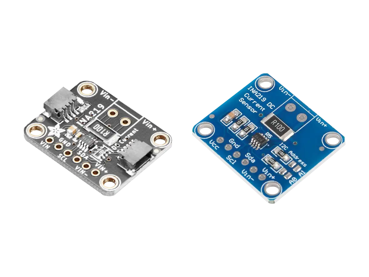
Adafruit has an INA219 breakout board (PID 904) with a size of 25.6mm x 20.4mm(1.0in x 0.8in) that uses either the INA219A or INA219B version of the chip.
Adafruit INA219 Breakout Board
Adafruit INA219 Board Layout (Top View)
The Adafruit board has a 0.1Ω 1% shunt resistor across the Vin+ and Vin- pins that
can measure up to 3.2A with ±0.8mA resolution. The load supply voltage is measured across the Vin- and GND pins
with the range of 0V to 26V DC.
The board comes with a 6-pin header, so you can easily attach this sensor
to a breadboard, as well as a 3.5mm terminal plug so you can easily attach and detach your load. On each side of
the board are STEMMA QTSTEMMA QT ('cutie') connectors are Adafruit's name for 4-pin JST SH connectors with 1.0mm pitch. These connectors were implemented on Adafruit boards to make it easy to plug-n-play various sensors and devices without soldering and wiring. The STEMMA QT (JST SH) are a smaller connector than the STEMMA (JST PH) that do not fit on smaller boards. STEMMA QT is cross-compatible with SparkFun Qwiic connectors. connectors for supplying power VCCVoltage Collector Collector (VCC) is the supply voltage at the collector of a transistor. The double subscript notation of repeating letters "CC" is used to denote a power supply voltage that is relative to ground. to the chip and
the two I2CInter-Integrated Circuit. Also referred to as IIC or I2C. lines (SCLSerial Clock (SCL) is the output clock signal line from the master device. Also referred to as SCK, SCLK, or CLK. and SDASerial Data Line).
Adafruit has a tutorial for their INA219 board, with assembly, hookup wiring, Arduino code, and CircuitPython
code, schematics, and PCB.
Generic breakout boards for the INA219, like the one shown in the figure below, are also available. These
generic boards are similar to the Adafruit board, but have a different board layout and do not have the
STEMMA QT connectors, but you can use the Adafruit Arduino library with them.
Generic INA219 Module
More details on both of these INA219 modules can be found in the articles below.
Created:
27Jul2024 20:13:46 UTC
2024-07-27T20:13:46Z
Updated:
24Aug2024 21:30:55 UTC
2024-08-24T21:30:55Z
Rating: (0 reviewsThis article has not been rated yet)
The INA219 High-Side DC Power Shunt Sensor IC measures voltage, current, and power with a shunt resistor and outputs
the results over an I2C interface. Adafruit and generic breakout boards for the INA219 IC are available with external
circuitry and pin through holes to make it easy to interface to.
Created:
22Jul2024 00:57:00 UTC
2024-07-22T00:57:00Z
Updated:
04Aug2024 04:03:44 UTC
2024-08-04T04:03:44Z
Rating: (0 reviewsThis article has not been rated yet)
Measure DC voltage, current, and power with the INA219 Module and Arduino Uno R3
Created:
24Jul2024 02:03:09 UTC
2024-07-24T02:03:09Z
Updated:
04Aug2024 03:56:00 UTC
2024-08-04T03:56:00Z
Rating: (0 reviewsThis article has not been rated yet)
Measure DC voltage, current, and power with the INA219 Module and RPi Pico
The INA226 is a current shunt and power monitor with an I2C interface. The device monitors both a shunt voltage
drop, either high-side or low-side sensing, and the bus
supply voltage (0V to 36V). It operates from a single
2.7V to 5.5V supply, drawing a typical of 330μA of supply current.
Generic breakout boards for the INA226 are available like the one shown in the figure below.
Generic INA226 Module
Generic INA226 Board Layout
The generic boards usually have a 0.1Ω 1% shunt resistor across the IN+ and IN- pins
that can measure up to 800mA. The bus voltage is measured across the VBS and GND pins with a range of
0V to 36V DC.
The ALERT pin labeled ALE is a mult-function alarm output that is programmed to respond to a
user-defined event: shunt current over/under limit, bus
voltage over/under limit, power over limit, or a Conversion Ready state to inform the
user when the device has completed the previous conversion and is ready to begin a new conversion.
Communication
with the board is through I2C with the SCL and SDA pins. There are INA226 Arduino libraries available to
communicate over I2C, with two examples on GitHub are listed below.
The INA260 IC is a high/low side current shunt and power monitor with an I2C
interface. The main difference between the INA260 and INA226 is that the INA226 needs an external shunt while
the INA260 has one built-in.
The INA260 monitors both the shunt voltage drop and the bus voltage supply on an external load and operates from
a single 2.7V to 5.5V supply. Both the INA219 and INA260 chips are used to monitor
the voltage and current. The main difference between the two is that INA219 is
high-side only, while INA260 does both high and low side.
Adafruit has an INA260 breakout board (PID 4226) the size of 22.9mm x 22.8mm(0.9in x 0.9in) shown in the figure below.
Adafruit INA260 Breakout Board
Adafruit INA260 Board Layout
The INA260 IC has an internal 2mΩ 1% shunt resistor across the Vin+ and Vin- pins
that can measure up to 15A continuous with ±1.5mA resolution. The load supply voltage is measured across the
VBus and GND pins with the range of 0V to 36V DC.
The board comes with an 8-pin header, so you can easily attach this sensor to a
breadboard, as well as a 3.5mm terminal plug so you can easily attach and detach your load.
The data communication is over two I2C lines (SCL and SDA). Adafruit provides an
Arduino library and CircuitPython library on GitHub for communicating with the device over I2C. These libraries
read in the bus voltage in mV, current in mA, and power in mW.
The Alert pin is a mult-function alarm output that is programmed to respond to a
user-defined event: shunt current over/under limit, bus
voltage over/under limit, power over limit, or a Conversion Ready state to inform
the user when the device has completed the previous conversion and is ready to begin a new conversion.
Adafruit has a tutorial for their INA219 board, with assembly, hookup wiring, Arduino code, and CircuitPython
code, schematics, and PCB.
The INA3221 is a three-channel, high-side current and
bus voltage monitor with an I2C interface. The INA3221 monitors both shunt voltage drops and bus supply voltages,
in addition to having programmable conversion times and averaging modes for these signals. This IC also features
alerts to detect multiple programmable out of range conditions for each channel.
Generic breakout boards for the INA3221 are available like the one shown in the figure below. The size of these
boards are about 38mm x 32mm.
Generic INA3221 Module
The generic boards usually have a 0.1Ω 1% shunt resistors across each of the
3 channels that can measure up to 1.6A on each channel. The operating supply voltage
of 2.7V to 5.5V is connected across the VS to GND pins. The bus voltage is measured
across the VIN1+/VIN2+/VIN3+ and GND pins with a range of
0V to 26V DC.
Generic INA3221 Board Layout
Generic INA3221 Module Pin Functions
Pin Name
Function
VS
The operating supply voltage of 2.7V to 5.5V is connected across the VS to GND
pins.
VIN1-
Connect to load side of the channel 1 shunt resistor. Bus voltage is the
measurement from this pin to ground.
VIN1+
Connect to supply side of the channel 1 shunt resistor.
VIN2-
Connect to load side of the channel 2 shunt resistor. Bus voltage is the
measurement from this pin to ground.
VIN2+
Connect to supply side of the channel 2 shunt resistor.
VIN3-
Connect to load side of the channel 3 shunt resistor. Bus voltage is the
measurement from this pin to ground.
VIN3+
Connect to supply side of the channel 3 shunt resistor.
CRI
The Critical pin is a digital output alert that monitors individual conversions of each shunt voltage
channel to determine if they exceed a programmed limit value.
WAR
The Warning Alert pin is a digital output that monitors the averaged value of each shunt voltage channel
to determine if they exceed a programmed limit value.
PV
The Power-Valid Alert pin is a digital output that verifies if all power rails are above the required levels.
VPU
The VPU pin is an analog input pull-up supply voltage
(0V to 26V) used to bias power valid output circuitry.
TC
The Timing-Control Alert pin is a digital output to verify proper power-supply
sequencing.
SCL
I2C serial clock line; open-drain input.
SDA
I2C serial data line; open-draininput/output.
There are INA3221 Arduino libraries available to communicate over I2C
(e.g., Tinyu's INA3221 Arduino Library
given in the Arduino website).
The MAX471 IC made by Maxim (a subsidiary of Analog Devices) is a bidirectional
high-sidecurrent-sense amplifier that produces an
analog output voltage proportional to the input current (outputs 1 Volt/Amp). It is
typically used for battery or DC power-line monitoring.
The MAX471 has an internal 35mΩ current-sense resistor and measures currents up to
±3A. The MAX471 also has an open-collector SIGN output that indicates current-flow
direction, so the user can monitor whether a battery is being charged or discharged.
The MAX471 IC is obsolete and no longer manufactured by Analog Devices
(see
MAX471 Product Page),
so it is not recommended for newer designs. However, the MAX471 IC is still available on the market in a many
products and breakout boards like the diymore MAX471 module shown below.
diymore MAX471 Module
diymore MAX471 Board Layout
The load current is measured with the MAX471 IC that outputs an analog voltage of
1 Volt/Amp on the AT pin. The load voltage is measured by reducing the VIN voltage
5x with a resistor voltage divider to an analog output on the VT pin.
The VIN input voltage range the MAX471 can handle is 3V to 36V DC. However, a VIN of
36V will give 36V/5 = 7.2V output on the VT pin, which may be too high for an ADC
reading the VIN pin.
If you are using a 5V ADC, then the VIN range should be limited from
3V to 25V.
If you are using a 3.3V ADC, the VIN range is reduced 3V to 16.5V.
There is no protection circuitry between the VIN input and the VT output, so caution must used if
over-voltage on VIN is possible.
The PZEM-003 module by Peacefair is used for measuring DC voltage, current, active power, and energy
consumption, where the data is read through an RS485RS485 (or RS-485) is a standard defining the electrical characteristics of serial lines for serial communications systems. It allows multiple 485 devices on the same bus and adopts a balanced transmission and differential reception with the ability to suppress common mode interference. interface with a baud rate of 9600bps.
PZEM-003 DC Module
This module measures voltages directly with a range from 5mV to 300V and measures
current using an internal shunt resistor with a range from 0.01A to 10A
(a different PZEM-017 module is for measuring higher currents from 0.02A up to
300A using an external shunt resistor). The module usually comes with an RS485 to USB adapter to allow a
computer to read the data through the USB port.
A basic hookup diagram for the PZEM-003 DC Module is shown below.
PZEM-003 DC Module Hookup for PC
The module is powered by the load power supply if the voltage is > 7V. When the
input voltage is < 7V, power needs to be supplied by the micro USB port on
the side of the module (Peacefair says that you should not use a PC USB port to supply power to the
PZEM-003 to avoid damage to the PC).
The RS485 data output of the module is over two wires, A and B, that can be connected to the USB adapter
provided. The output terminal also has +5V DC and ground lines to power alternative
interface devices (< 100 mA).
Peacefair has their own PC software for displaying the measured results in realtime, but has its limitations
especially when it comes to recording the data. However, the communication protocol is ModbusModbus or MODBUS is a client-server serial data communications protocol. A Modbus message contains a destination address, a command (e.g., read/write register), the data, and a check sum (LRC or CRC).
which can be read in by any programming language with a library that interprets Modbus
(e.g., MinimalModbus and PyModbus libraries are available in Python). The advantage of programming your
software is that you can both record the data and plot it in realtime.
The PZEM-003 DC Module can also be hooked up to a microcontroller using a
TTLTransistor-Transistor Logic to RS485 adapter shown below.
PZEM-003 DC Module Hookup for Microcontroller
The TTL to RS485 adapter is not included with the module and must be purchased separately. This is useful if what
your measuring is not near a computer. The microcontroller can either transfer the data over WiFi or
RFRadio Frequency to a computer or log the data internally in non-volatile memory
(e.g., EEPROMElectrically Erasable Programmable Read-Only Memory, Flash) or with an external memory module such as an
SDSecure Digital removable miniaturized flash memory cards card.
The PZEM-017 module by Peacefair is used for measuring DC voltage, current, active power, and energy consumption,
where the data is read through an RS485 interface with a baud rate of 9600bps. This module is similar to the
PZEM-003 with the same input voltage range of 5mV to 300V,
but it can measure higher currents from 0.02A up to 300A with an external shunt resistor.
PZEM-017 DC Module
There are 4 kinds of external shunts it can be matched with: 50A, 100A, 200A, and
300A. The module usually comes with an RS485 to USB adapter to allow a computer to read the data through the USB port.
A basic hookup diagram for the PZEM-017 DC Module is shown below.
PZEM-017 DC Module Hookup for PC
The module is powered by the load power supply if the voltage is > 7V. When the
input voltage is < 7V, power needs to be supplied by the micro USB port on the
side of the module (do not use a PC USB port to supply power to the PZEM-017 to
avoid damage to the PC).
The RS485 data output of the module is over two wires, A and B, that can be connected to the USB adapter
provided. The output terminal also has +5V DC and ground lines to power alternative
interface devices (< 100 mA). The same PC software by Peacefair that was
mentioned for the PZEM-003 can also be used for PZEM-017.
The PZEM-017 DC Module can also be hooked up to a microcontroller using a TTL to RS485 adapter shown below.
PZEM-017 DC Module Hookup for Microcontroller
The TTL to RS485 adapter is not included with the module and must be purchased separately. This is useful if
what your measuring is not near a computer. The microcontroller can either transfer the data over WiFi or
RFRadio Frequency to a computer or log the data internally in non-volatile
memory (e.g., EEPROMElectrically Erasable Programmable Read-Only Memory, Flash) or with an external memory module
such as an SDSecure Digital removable miniaturized flash memory cards card.
The AC power modules in this section can be used for mains electricity to measure RMSRoot Mean Square voltage,
RMS current, power factor, frequency, and energy consumption.
Voltage Measurement:
The RMS voltage is measured directly from the power hot line (L) and return
Neutral (N) using a step down transformer.
Current Measurement:
The RMS current is measured by a shunt resistor for lower currents or a current transformer (CT) for higher
currents. Greater accuracy is obtained with a shunt resistor at the cost of a limited range of current that can
be measured. The convenience of a split core current transformer is that it can be clamped onto the current
carrying wire without breaking the circuit.
Power Factor:
The power factor in AC circuits relates the apparent power (the product of the RMS current and RMS
voltage) to the real power absorbed by a load. The real power is the average of the instantaneous
product of voltage and current and represents the capacity for performing work.
AC Power Factor Equation
The power factor typically has values between 0 and 1.0, although it is possible
that negative values from -1.0 to 0 to occur when the load generates power that
flows back to the source. Purely resistive circuits have a power factor of 1.0. Values lower than 1.0 occur in
circuits with reactive components (i.e., capacitors, inductors) where AC voltage and current are not in
phase that reduces the average product of the two.
Frequency:
The frequency of an AC circuit is the number cycles per second, expressed as HZ, that quantifies how often an AC
voltage or current wave repeats itself. For mains electricity, this is usually between
50Hz to 60Hz.
Energy Consumption:
The amount of energy an AC circuit load consumes from a power source is the product of the power
(in Watts) consumed by the load and the time (in hours).
Energy consumption can be expressed in Wh (watt-hours) or
kWh (kilo-watt-hours).
There are different AC power modules available listed in the table below with their own capabilities and
measurement ranges.
AC Power Sensor Comparison Table
Model
Voltage Measurement
Current Measurement
Power Factor
Frequency
Output
PZEM-004T-10A
80V to 260VAC RMS
0 to 10A
1mΩ Internal Shunt
Low Side
0 to 1.00
45Hz to 65Hz
2-Wire TTL to USB
PZEM-004T-100A
80V to 260VAC RMS
0 to 100A
External CTCurrent Transformer
0 to 1.00
45Hz to 65Hz
2-Wire TTL to USB
PZEM-014
80V to 260VAC RMS
0 to 10A
1mΩ Internal Shunt
Low Side
0 to 1.00
45Hz to 65Hz
2-Wire TTL to USB
PZEM-016
80V to 260VAC RMS
0 to 100A
External CTCurrent Transformer
0 to 1.00
45Hz to 65Hz
2-Wire TTL to USB
The input current measurement range depends on the usage of a shunt resistor or current transformer, where more
accuracy is obtained with a shunt resistor at the cost of a limited range of current that can be measured. The
output of these devices is a digital signal (TTL) that is converted to USB signal with an TTL to USB adapter so a
computer can read and display the data.
The PZEM modules have their own PC software that displays the measurements in real time, however the communication
protocol is ModbusModbus or MODBUS is a client-server serial data communications protocol. A Modbus message contains a destination address, a command (e.g., read/write register), the data, and a check sum (LRC or CRC). which can be read in by any programming language with a library that
interprets Modbus (e.g., MinimalModbus and PyModbus libraries are available in Python).
The PZEM-004T-10A module by Peacefair is used for measuring AC voltage, current, active power, power factor,
frequency, and energy consumption, where the data is read through an TTL interface with a baud rate of 9600bps.
The input voltage can range from 80V to 260V RMSRoot Mean Square.
PZEM-004T-10A AC Module
This module uses an internal shunt resistor to measure current with a range of 0 to 10A
(a different PZEM-004T-100A module is used to measure higher currents up to 100A).
The module can interface directly with a microcontrollers UARTUniversal Asynchronous Receiver-TransmitterRXReceive and
TXTransmit serial port or with a computer using a TTL to USB adapter.
A basic hookup diagram for the PZEM-004T-10A AC Module is shown below.
PZEM-004T-10A AC Module Hookup for PC
The module is powered by +5V DC from the TTL to USB adapter. The TTL data output of
the module is over two wires, RXReceive and TXTransmit, that is connected to the USB
adapter for a computer.
Peacefair has their own PC software for displaying the measured results in realtime, but has its limitations
especially when it comes to recording the data. However, the communication protocol is ModbusModbus or MODBUS is a client-server serial data communications protocol. A Modbus message contains a destination address, a command (e.g., read/write register), the data, and a check sum (LRC or CRC).
which can be read in by any programming language with a library that interprets Modbus
(e.g., MinimalModbus and PyModbus libraries are available in Python). The advantage of programming your
software is that you can both record the data and plot it in realtime.
The PZEM-004T-10A AC Module can also be hooked up to a microcontroller as shown below.
PZEM-004T-10A AC Module Hookup for Microcontroller
The TTL to USB adapter is not included with the module and must be purchased separately. This is useful if what
your measuring is not near a computer. The microcontroller can either transfer the data over WiFi or
RFRadio Frequency to a computer or log the data internally in non-volatile memory
(e.g., EEPROMElectrically Erasable Programmable Read-Only Memory, Flash) or with an external memory module such as an
SDSecure Digital removable miniaturized flash memory cards card.
The PZEM-004T-100A module by Peacefair is similar to the PZEM-004T-10A, with the
same 80V to 260V AC RMSRoot Mean Square input voltage, but can measure currents up
to 100A using an external Current Transformer (CT). Like the PZEM-004T-10A, it is
used for measuring AC voltage, current, active power, power factor, frequency, and energy consumption, where the
data is read through an TTL interface with a baud rate of 9600bps.
PZEM-004T-100A AC Module
A basic hookup diagram for the PZEM-004T-100A AC Module for a PC is shown below.
PZEM-004T-100A AC Module Hookup for PC
The hot Line (L) and Neutral (N) from a wall outlet is
plugged directly to the input terminal for the voltage measurement. The CTCurrent Transformer is clamped around
the Neutral (N) wire coming out of the load for the current measurement.
The module is powered by +5V DC from the TTL to USB adapter. The TTL data output of
the module is over two wires, RXReceive and TXTransmit, that is connected to the USB
adapter for a computer. The same PC software by Peacefair that was mentioned for the
PZEM-004T-10A can also be used for PZEM-004T-100A.
The PZEM-004T-100A AC Module can also be hooked up to a microcontroller as shown below in the same way as the
PZEM-004T-10A.
PZEM-004T-100A AC Module Hookup for Microcontroller
The PZEM-014 module by Peacefair is used for measuring AC voltage, current, active power, power factor,
frequency, and energy consumption, where the data is read through an an RS485 interface with a baud rate of
9600bps.
PZEM-014 AC Module
The main difference from the PZEM-004T-10A is instead of a TTL interface it
has an RS485 interface that can connect with a computer using the provided RS485 to USB adapter. The
PZEM-014 also has a plastic enclosure. It is similar to the
PZEM-004T-10A with the input voltage range from
80V to 260V RMSRoot Mean Square and an internal shunt resistor to measure current
with a range of 0 to 10A (a different PZEM-016
module is used to measure higher currents up to 100A with an external CTCurrent Transformer).
A basic hookup diagram for the PZEM-014 AC Module is shown below.
PZEM-014 AC Module Hookup for PC
The hot Line (L) and Neutral (N) from a wall outlet is
plugged directly to the input terminal for the voltage measurement and to provide power to the module. An internal shunt
resistor is used to measure the current.
The RS485 data output of the module is over two wires, A and B, that can be connected to the USB adapter
provided. The output terminal also has +5V DC and ground lines to power alternative
interface devices (< 100 mA). The PC software by Peacefair is the same one used
by the PZEM-004T-10A and PZEM-004T-100A.
The PZEM-014 Module can also be hooked up to a microcontroller using a TTL to RS485 adapter shown below. The TTL
to RS485 adapter is not included with the module and must be purchased separately.
The PZEM-016 module by Peacefair is used for measuring higher AC current than the
PZEM-014, with similar measurements of voltage, active power, power factor,
frequency, and energy consumption, where the data is read through an RS485 interface with a baud rate of 9600bps.
Like the PZEM-014, it can measure
80V to 260V AC RMSRoot Mean Square input voltage, but can measure currents up to
100A using an external Current Transformer (CT).
PZEM-016 AC Module
A basic hookup diagram for the PZEM-016 AC Module for a PC is shown below.
PZEM-016 AC Module Hookup for PC
The hot Line (L) and Neutral (N) from a wall outlet is
plugged directly to the input terminal for the voltage measurement and to provide power for the module. The
CTCurrent Transformer is clamped around the Neutral (N) wire coming out of the load
for the current measurement.
The RS485 data output is the same as the PZEM-014 over
two wires, A and B, that can be connected to the USB adapter provided. The output terminal also has
+5V DC and ground lines to power alternative interface devices
(< 100 mA). The PC software by Peacefair is the same one used by the
PZEM-014, PZEM-004T-10A, and
PZEM-004T-100A.
The PZEM-016 Module can also be hooked up to a microcontroller using a TTL to RS485 adapter shown below. The
TTL to RS485 adapter is not included with the module and must be purchased separately.
What was covered here were power sensor modules that are common on the market that can measure
DC/AC voltage and current on one board. You can also combine two separate voltage and
current sensors to compute the power and energy consumption in software (either in the embedded firmware on a
microcontroller or a computer program). However, having power measurements made on a single board is more
convenient to setup with less hardware and software programming.


(0) Comments
Sign in to leave a comment
Sign In