Temperature Sensors Overview
Updated: 26Aug2024 02:25:56 UTC 2024-08-26T02:25:56Z
Rating: (0 reviewsThis article has not been rated yet)
This overview of temperature sensors covers electronic components and devices that provide an analog or digital voltage output that corresponds to the temperature being measured. The scope of this overview will focus on five common categories of temperature sensors given below.
- Thermistors:
- A thermistor is a semiconductor type resistor that is more sensitive to temperature than your standard resistors. They typically have a high sensitivity and fast response time, but are very nonlinear.
- Thermocouples:
- A thermocouple measures temperature by using a pair of wires made of different metals, where the ends of the wires are often joined by a welding spot. The different thermoelectric characteristics of the two wires generates a small voltage across them that is dependent on their temperature. Thermocouples have the widest temperature range than any other form of contact temperature sensor, with a range from about -200°C to +1200°C, although some are capable of measuring up to 1800°C.
- Resistance Temperature Detectors (RTDs):
- A Resistance Temperature Detector (RTDResistance Temperature Detector), also known as a resistive temperature device, has a metal film or filament as its sensing element with a resistance that increases with temperature. An RTD is used when high precision and stability is needed.
- Semiconductor IC Temperature Sensors:
- Temperature sensors in the form of an ICIntegrated Circuit typically measure temperature using the semiconductor pn-junction of a diode or bipolar transistor that has a strong thermal dependence. These sensors are very linear and are easy to interface.
- IR Temperature Sensors:
- IRInfrared temperature sensors respond to infrared radiation emitted from an object and measure the average temperature of the object's surface area in the sensor's Field Of View (FOVField Of View). They are non-contact sensors that are used in circumstances where direct contact temperature measurements are not desirable, difficult, or impossible.
| Thermistor | Thermocouple | RTD | IC | IR | |
|---|---|---|---|---|---|
| Temperature Range |
50°C to 300°C | -200°C to +1200°C | -200°C to 600°C | -55°C to 150°C |
|
| Sensitivity | High | Moderate | Low | Highest | Low |
| Accuracy | Low to Moderate | Moderate | High | Low to High | Low |
| Response Time |
Fast | Slow to Fast | Slow | Slow | Fast |
| Linearity | Exponential | Fairly Linear | Fairly Linear | Linear | Fairly Linear |
| Cost | Low | Moderate to High | High | Low to Moderate | Moderate |
Thermistors
A thermistor is a semiconductor type resistor that is more sensitive to temperature than your standard resistors that can measure temperatures from -50°C up to 300°C. They are made of metallic oxides, pressed into a bead, disk, or cylindrical shape that is enclosed in a protective outer sheath using an impermeable material such as epoxy or glass.
Epoxy and glass coated thermistors have different temperature ranges. Epoxy coated thermistors have a bead diameter typically between 0.075mm to 5mm, can withstand temperatures from -50°C and 150°C, and are generally used to detect the ambient temperature with corrosion resistance. Glass coated thermistors, with bead diameters typically between 0.4mm to 10mm, can withstand temperatures up to 300°C for high temperature applications such as 3D printing.
You may also see disk shaped NTCNegative Temperature Coefficient thermistors called inrush current limiters, which are mainly used to limit the inrush of current that tends to occur when a circuit is switched on rather than for temperature sensing applications.
All thermistors are divided into two groups: Negative Temperature Coefficient (NTC) and Positive Temperature Coefficient (PTC). The NTC thermistor is the most common type where its resistance decreases as temperature increases. The PTC thermistor resistance increases as the temperature increases.
Both NTC and PTC thermistors are highly nonlinear as illustrated in the figure below (this plot may appear flatter in datasheets because they are plotted on a logarithmic scale). The nonlinear relationship of temperature and resistance is specified in the datasheet of the thermistor in the form of a table and/or coefficients using a model such as the Steinhart-Hart equation or a simpler B (or β) parameter equation (see Wikipedia Thermistor).
NTC thermistors are more common than PTC thermistors for temperature sensing applications because they have a higher sensitivity over a larger temperature range, are more tolerant of variations in current, and often cost less.
NTC thermistors are referred to by their resistance at room temperature (25°C) that come in values of 5K, 10K, 15K, 20K, 50K, 100K, 150K, and 200K Ohms. For example, a 10k NTC thermistor has 10k Ohm resistance at 25°C and a 100k NTC thermistor has 100k Ohm resistance at 25°C. The 10k NTC thermistor is for lower temperature environments below 100°C and typically encapsulated with epoxy resin to provide corrosion resistance in damp environments to measure the ambient temperature. The 100k NTC thermistor is often sealed with glass to ensure stable use in high temperature environments from 100°C to 250°C.
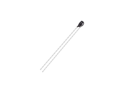
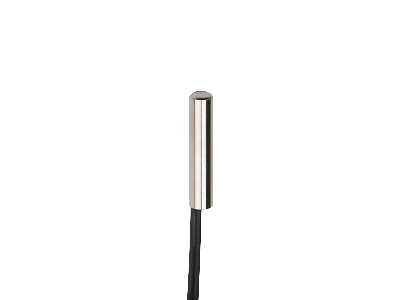
NTC thermistors are available as components, probes, and modules.
- Components offer the flexibility to mount it on a PCBPrinted Circuit Board board or connect your own wire with the desired length.
- Epoxy and stainless steel probes seal the thermistor to protect against corrosion, making them useful in damp environments and even waterproof.
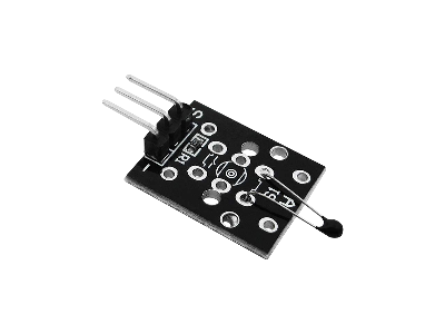
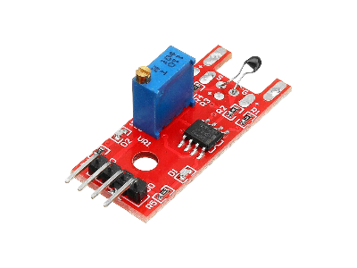
- Modules are convenient to use with all the circuitry needed to read the measurements with an ADCAnalog-to-Digital Converter (ADC, A/D, or A-to-D) or microcontroller.
The Keyes KY-013 module (3cm x 1.5cm) simply provides the voltage divider for you by adding an extra 10kΩ resistor to produce an analog voltage output. The KY-028 module (3.6cm x 1.5cm) also has a trim potentiometer to adjust the analog output level and temperature threshold for a HIGH/LOW digital output using an LM393 comparator ICIntegrated Circuit.
Thermocouples
Thermocouples have the widest temperature range than any other form of contact temperature sensor. They typically range from about -200°C to +1200°C, although some are capable of measuring up to 1800°C.
A thermocouple measures temperature by using a pair of wires made of different metals, where the ends of the wires are often joined by a welding spot. The different thermoelectric characteristics of the two wires generates a small voltage across them that is dependent on their temperature. The voltage generated by a thermocouple is extremely small (in microvolts per °C) and needs to be amplified.
Different types of thermocouples are identified by ANSIAmerican National Standards Institute standard codes, consisting of single letters of the alphabet shown in the table below, with the most common being the K-Type. The wire color coding standards in the US (ANSI) are different than the international standard (IECInternational Electrotechnical Commission).
| Type | Temperature Range |
Sensitivity (μV/°C) |
Description |
|---|---|---|---|
| K | -250°C to +1350°C | 41 μV/°C | The most popular type of thermocouple, commonly used in 3D printers. Positive wire is a nickel-chromium alloy and the negative wire is a nickel-aluminum alloy. |
| J | -200°C to +1200°C | 55 μV/°C | Has a slightly less range than type K but higher sensitivity. The iron wire is magnetic and vulnerable to corrosion. Positive wire is iron and negative wire is a copper-nickel alloy. |
| T | -250°C to +400°C | 43 μV/°C | Used for cryogenic applications. Positive wire is copper and the negative wire is a copper-nickel alloy. |
| E | -250°C to 1000°C | 68 μV/°C | Most sensitive type with the highest coefficient. Positive wire is a nickel-chromium alloy and the negative wire is a copper-nickel alloy. |
| N | -250°C to 1300°C | 39 μV/°C | More stable at higher temperatures than the K-Type with a sensitivity. Positive wire is a nickel-chromium alloy and the negative wire is a nickel-silicon-magnesium alloy. |
| R | -50°C to 1750°C | 10 μV/°C | For high temperature applications with a low temperature coefficient. Similar to Type S, but offer improved stability and a marginal increase in range. Positive wire is a platinum-rhodium alloy and the negative wire is platinum. |
| S | -50°C to 1750°C | 10 μV/°C | For high temperature applications with a low temperature coefficient. Highly reproducible and a laboratory standard. Positive wire is a platinum-rhodium alloy and the negative platinum. |
| B | 0°C to 1820°C | 10 μV/°C | Type B is very similar to type R and S, but operate at higher temperatures. It is also less susceptible to grain growth and drift. Both the positive and negative wires are a platinum-rhodium alloy. |
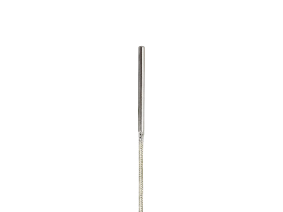
Thermocouple probes are either ungrounded, grounded, or exposed.
- Ungrounded Thermocouple Probes:
- The junction is isolated from the probe sheath, making them less susceptible to noise and more accuracy, but slower response times.
- Grounded Thermocouple Probes:
- Tthe junction is welded to the probe sheath that creates a more efficient heat transfer resulting in faster response time, but are more susceptible to noise and ground loops that make them less accurate. Ground loops can occur when the sensor is connected to earth ground at the point of measurement and the wires are connected to a device that is grounded in another location, causing the two grounds to be at a different voltage potential.
- Exposed Thermocouple Probes:
- The junction is outside the probe sheath and exposed to the target medium. This type is suitable for measuring non-corrosive static liquids, gases, or air. However, high heat and corrosive environments can damage the junction.
The wire insulation of thermocouples are typically vinyl or fiberglass braided, which have different temperature ranges. Vinyl insulation can melt at around 150°C to 200°C, while fiberglass braid insulation is used for higher temperature measurements such as heaters and ovens and can withstand temperatures from 450°C to 650°C depending on the type of glass. One limitation to fiberglass insulation is that it is porous on its own, so it's not very good in wet environments. There are also stainless steel overbraided covers used as a more rugged abrasion resistor outer shield over fiberglass insulation for the wires.
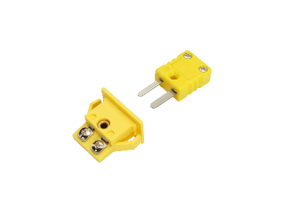
The end of a K-Type probe that connects to an amplifier device can have either bare wires, spade/fork terminal connectors, or a standard flat pin male connector (some have round pin connectors). Bare wires or the spade/fork connectors work good with a screw terminal block on an amplifier board. The standard flat pin male connectors are easier to plug/unplug, but would require a PCC-SMP-K female connector on the PCBPrinted Circuit Board of the amplifier device or other suitable female adapter (e.g., screw terminal adapter, banana plug adapter, etc.).
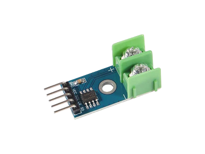
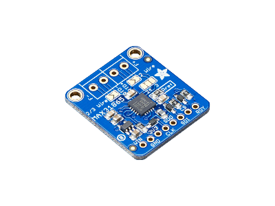
The most common amplifier module used for thermocouples is the MAX6675 IC available in generic breakout boards. Both Adafruit and SparkFun have different modules listed in the table below that vary in their temperature range, temperature resolution, and data output. Note that most thermocouples have an accuracy of about ±2°C or worse depending on the temperature and type, so the resolution of the amplifier will be a lot better than the accuracy.
| IC | Board | Type | Range | Resolution | Output |
|---|---|---|---|---|---|
| MAX6675 | Generic Board |
Type-K
Ungrounded |
0°C to +1024°C | ±0.25°C | Digital SPI |
| MAX31850K | Adafruit PID 1727 |
Type-K
Ungrounded |
-270°C to +1370°C | ±0.25°C | Digital 1-Wire |
| MAX31855K |
Adafruit PID 269
SparkFun SEN-13266 |
Type-K
Ungrounded |
-200°C to +1350°C | ±0.25°C | Digital 3-Wire SPI |
| MAX31856 | Adafruit PID 3263 | K, J, N, R, S, T, E, or B
Grounded / Ungrounded |
-210°C to +1800°C | ±0.0078125°C | Digital 4-Wire SPI |
| AD8495 | Adafruit PID 1778 |
Type-K
Grounded / Ungrounded |
-250°C to +750°C @ 5V VCC
-250°C to +410°C @ 3.3V VCC |
N/A | Analog |
| MCP9600 |
Adafruit PID 4101
SparkFun SEN-16295 |
K, J, T, N, S, E, B and R
Grounded / Ungrounded |
-250°C to +1800°C | ±0.0625°C | Digital I2C |
| MCP9601 | Adafruit PID 5165 |
K, J, T, N, S, E, B, and R
Grounded / Ungrounded |
-250°C to +1800°C | ±0.0625°C | Digital I2C |
Resistance Temperature Detectors (RTDs)
A Resistance Temperature Detector (RTD), also known as a resistive temperature device, has a metal film or filament as its sensing element with a resistance that increases with temperature. An RTD is used when high precision and stability is needed. Platinum (Pt) is the most common element used for RTDs because of its wide temperature range, accuracy, and stability.
RTDs differ from PTCPositive Temperature Coefficient thermistors which have a semiconductor sensing element. PTCs have higher sensitivity and are more responsive to changes in temperature with faster response time than RTDs, but are less stable and precise with a smaller temperature range than RTDs. Due to the RTD's low temperature coefficient, it requires sensitive electronics and signal conditioning to read the low resistance, while the current through the RTD should be restricted to about 0.5mA to 1mA to avoid self heating.
RTD probes and amplifiers are typically labeled PT100 or PT1000, which is referring to the resistance of 100 Ohms or 1000 Ohms at 0°C of a small strip of Platinum (Pt). Both the RTD PT100 and PT1000 are available in a similar range of tolerances with similar temperature coefficients. Since the resistance value readings for a PT1000 will be higher than a PT100 by a factor of 10x at the same temperature, this makes PT1000 more accurate for small temperature changes as they would result in larger changes in resistance when compared to the PT100.
An RTD probes come in two, three, and four wires as shown in the figure below. The two and three wire probes enables temperature compensation for the leads to an RTD. If only two wires are used, the leads will have an unknown resistance that will be affected by temperature. In the three wire design, the resistance of a single lead can be found by passing a test current through it and the third wire without passing through the sensing component. The resistance of the other lead can be inferred from the assumption that all the leads are identical in length and composition. In the four wire configuration, the resistance of both leads are measured.
The two wire configuration is more suitable for the PT1000, whereas the three and four wire configurations are better for the PT100. This is because the PT000 sensing element has greater resistance than the PT100, so the distorting effect of the resistance in the lead wires is less significant overall. Because resistance across the PT100 sensing element is considerably lower than the PT1000, unwanted resistance from lead wires and connectors will have a larger distorting effect on overall resistance measurements.
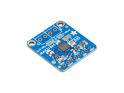
The most common RTD amplifier IC is the MAX31865 with a digital SPISerial Peripheral Interface output. Adafruit has two separate MAX31856 IC breakout boards for the PT100 (PID 3328) and PT1000 (PID 3328).
These boards can be used with 2, 3, or 4 wire configuration using solder jumper pads on the back of the board (the default configuration is 4 wire). The boards operate with a supply voltage and logic of 3V to 5V DC. The only difference between the PT100 and PT1000 boards is the reference resistor on the board (labeled Rref), where the PT100 version uses a 430Ω 0.1% resistor and the PT1000 uses a 4300Ω 0.1% resistor.
There are also MAX31856 PT100 and PT1000 RTD generic boards available. Sometimes these are misleadingly labeled PT100/PT1000, giving the impression you can easily switch between the PT100 and PT1000,but in fact you must change the default 430 Ohms reference resistance on the board (labeled Rref) for the PT100 by desoldering it and replacing it with a 4300 Ohms resistor for the PT1000.
RTD PT100 and PT1000 probes and amplifier products can be found in the links below.
Semiconductor IC Temperature Sensors
Temperature sensors in the form of an ICIntegrated Circuit typically measure temperature using the semiconductor pn-junction of a diode or bipolar transistor that has a strong thermal dependence. If the forward biased junction is connected to a constant current generator, the voltage across the junction is a measure of the junction temperature.
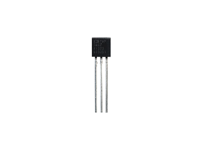
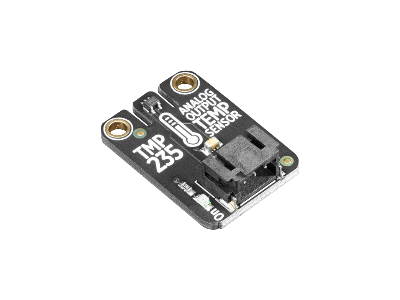
There are ICs, such as the LM35 and TMP36, that have an analog output proportional to the temperature (e.g., 10mV/°C). A comparison of common analog IC temperature sensors is given in the table below.
| IC | Temperature Range |
Accuracy | Operating Voltage |
Output | Datasheet |
|---|---|---|---|---|---|
| TMP235 | -50°C to +125°C | ±2.5°C | +2.3V to +5.5V | 10mV/°C | TMP235 Datasheet (PDF) |
| TMP36 | -40°C to +125°C | ±2°C | +2.7V to +5.5V DC | 10mV/°C | TMP36 Datasheet (PDF) |
| LM335 | -40°C to 100°C | ±2°C | +2.95V to +3.01V DC | 10mV/°K | LM335 Datasheet (PDF) |
| LM34 |
-45°C to 148°C
(-50°F to 300°F) |
±0.56°C
(±1.5°F) |
+5V to +30V DC | 10 mV/°F | LM34 Datasheet (PDF) |
| LM35DZ | 0°C to +100°C | ±0.5°C | +4V to +30V DC | 10mV/°C | LM35DZ Datasheet (PDF) |
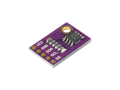
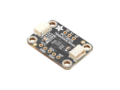
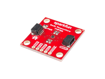
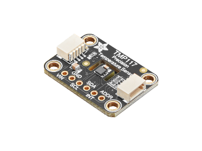
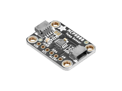
There are also ICs, such as the LM75, PCT2075, DS18B20, and MCP9808, that have an internal ADCAnalog-to-Digital Converter (ADC, A/D, or A-to-D) and output digital data over I2CInter-Integrated Circuit. Also referred to as IIC or I2C. or 1-Wire1-Wire is a half-duplex serial protocol using a single data line plus ground reference for communication.. A comparison of common digital IC temperature sensors is given in the table below.
| IC | Temperature Range |
Accuracy | Resolution | Operating Voltage |
Output | Datasheet |
|---|---|---|---|---|---|---|
| LM75B | -55°C to +125°C | ±2°C | ±0.125°C | +3.0V to +5.5V DC | I2C | LM75B Datasheet (PDF) |
| PCT2075 | -55°C to +125°C | ±2°C | ±0.125°C | +2.7V to +5.5V DC | I2C | PCT2075 Datasheet (PDF) |
| DS18B20 | -55°C to +125°C | ±0.5°C |
±0.0625°C
Configurable |
+3V to +5.5V DC | 1-Wire | DS18B20 Datasheet (PDF) |
| TMP102 | -55°C to +150°C | ±0.5°C | ±0.0625°C | +1.4V to +3.6V DC | I2C | TMP102 Datasheet (PDF) |
| MCP9808 | -40°C to +125°C | ±0.25°C |
±0.0625°C
Configurable |
+2.7V to +5.5V DC | I2C | MCP9808 Datasheet (PDF) |
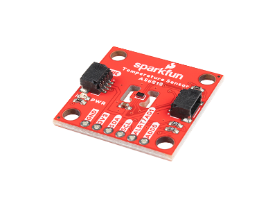
| AS6212 | -40°C to +125°C | ±0.2°C | ±0.0078°C | +1.7V to +3.6V DC | I2C | AS6212 Datasheet (PDF) |
| TMP117 | -55°C to 155°C | ±0.1°C | ±0.0078°C | +1.8V to +5.5V DC | I2C | TMP117 Datasheet (PDF) |
The TMP36, LM335, LM34, LM35, and DS18B20 are commonly found in the standard 3-Pin TO-92 package. The LM75, PCT2075, and MCP9809 are commonly found in 8-Pin SOICSmall Outline Integrated Circuit SMDSurface Mount Devices where you can find breakout boards available.
Infrared Temperature Sensors
All the temperature sensors discussed so far are contact sensors, meaning they measure temperature of an object, liquid, gas by being in contact with it. There are circumstances where direct contact temperature measurements are not desirable, difficult, or impossible, due to its location, large surface area, movement, contamination, or wide temperature range. This is where a non-contact infrared (IRInfrared) temperature sensor can be used.
IR temperature sensors respond to IR radiation emitted from an object and measures the average temperature of the object's surface area in the sensor's Field Of View (FOVField Of View). The FOV of the sensor is coned shaped and determines the relationship between the distance to the object and the area to be observed.
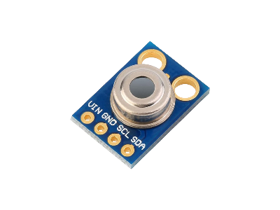
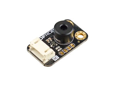
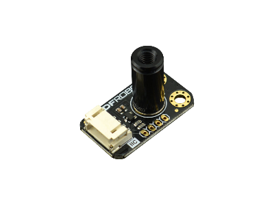
The MLX90614 sensor has an integrated IR sensitive thermopile detector chip and the signal conditioning ASICAplication-Specific Integrated Circuit in the same TO-39 can with an I2CInter-Integrated Circuit. Also referred to as IIC or I2C. or SMBusSystem Management Bus compatible interface.
The MLX90614 sensor has an object temperature range of -70°C to +380°C with a resolution of 0.02°C and accuracy of 0.5°C over wide temperature range (0°C to +50°C for both sensor and object temperature). The FOV of the sensor is 90 degrees, which means that for every 1cm you move away from an object, the diameter of the circular sensing area increases by 2cm. This sensor is available in 3V and 5V supply voltage versions.
There are MLX90614 breakout boards available with an onboard 3.3V voltage regulator that allows supply voltages from 3.6V to 5.5V. The MLX90614 offers a standard accuracy of ±0.5°C around room temperatures, while the medical-grade MLX90614-DCC offers an accuracy of ±0.2°C in a limited temperature range around the human body temperature. Boards also come with different lenses and FOV angles for larger distance ranges, like the MLX90614-DCI with a 5° FOV.










(0) Comments
Sign in to leave a comment
Sign In