HC-12 RF Transceiver
&
Raspberry Pi Pico (MicroPython)
Updated: 13Aug2024 01:11:20 UTC 2024-08-13T01:11:20Z
Rating: (0 reviewsThis article has not been rated yet)
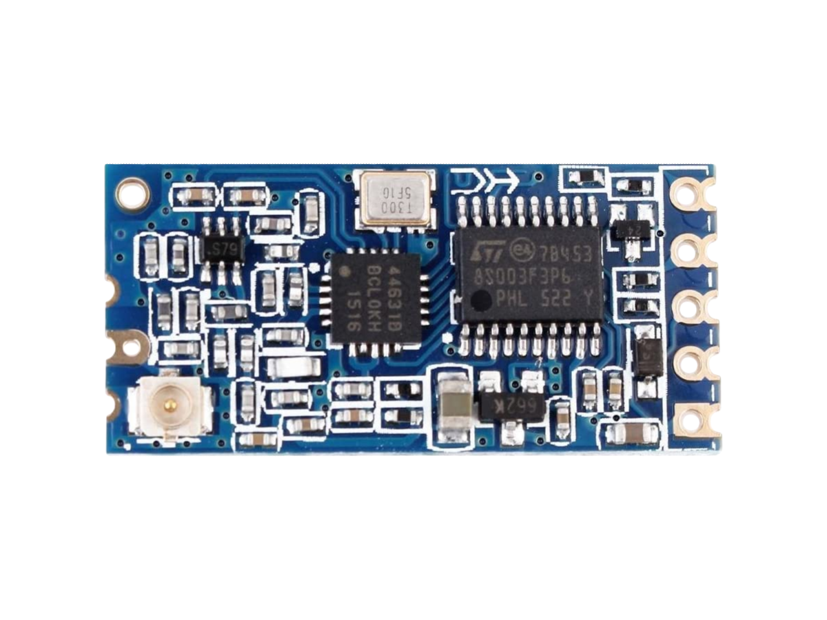
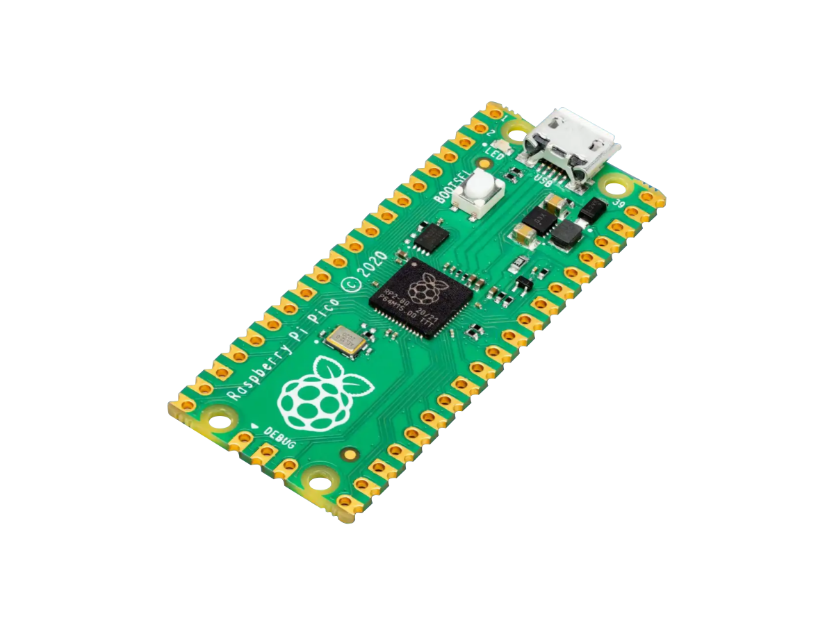
The HC-12 wireless RF transceiver modules can be controlled by an Raspberry Pi (RPiRaspberry Pi) microcontroller to establish two-way half-duplex wireless communication. The microcontroller can configure the HC-12 and send/receive messages over 2-Wire (TXTransmit, RXReceive) UARTUniversal Asynchronous Receiver-Transmitter.
In this tutorial, wireless text messages will be sent from a transmitting pair of Pico and HC-12 modules to a receiving pair using the UARTUniversal Asynchronous Receiver-Transmitter pins on the Pico. The transmitting Pico and HC-12 pair will be a stand-alone device connected to an external power source. The receiving Pico and HC-12 pair will be connected to a computer over USBUniversal Serial Bus, where a Python program on the computer will be used to read in the messages over the serial port and display them on the console.
The contents of this tutorial include the hardware wiring setup, software Python and Pyserial setup, Pico transmitter code, Pico receiver code, and Computer Python code.
Setup
RPi Pico Pinout
There are 5 different UARTUniversal Asynchronous Receiver-Transmitter (TXTransmit, RXReceive) physical pin pairs on the Pico board, as shown in the figure below, that can be used for UARTUniversal Asynchronous Receiver-Transmitter serial communication: pins (1, 2), (6, 7), (11, 12), (16, 17), and (21, 22).
Powering the Pico can be done by the 5V Micro USBUniversal Serial Bus port, 5V VBUS pin 40, or 1.8V to 5.5V across the VSYS pin 39. The HC-12 has a voltage supply rating of 3.2V to 5.5V DC, so if the 5V Micro USBUniversal Serial Bus port is used to power the Pico, then the HC-12 can be powered by the Pico's VBUS pin 40, VSYS pin 39, or 3.3V pin 36.
HC-12 Pinout
The pinout for the HC-12 module is given in the figure below. The setup in this tutorial uses the factory default firmware settings on the HC-12 module, so only the power and serial pins 1 through 4 will be used and there is no need to hook up the SET pin (connecting the SET pin to ground will put HC-12 in a configuration mode where settings can be changed).
Pico & HC-12 Wiring
The wiring between the Pico and HC-12 on both the receiver and transmitter in this tutorial will use the physical pins (21, 22), also labeled GPIO pins (GP16, GP17), on the Pico board for UART0 (TXTransmit, RXReceive). These pins on the Pico are conveniently on the same side of the board as the power pins that can be used to power the HC-12 module for the transmitter. The (TXTransmit, RXReceive) connections between the Pico and HC-12 need to be crossed, where the Pico TXTransmit pin is connected to the HC-12 RXDReceive Data pin and the Pico RXReceive pin is connected to the HC-12 TXDTransmit Data pin.
Python & PySerial
Both Python and the PySerial package must first be installed on the computer to read in microcontroller data over USBUniversal Serial Bus. Also, when connecting the microcontroller to the computer with a USBUniversal Serial Bus cable, the USBUniversal Serial Bus device on the computer needs to be identified to establish a connection.
Python can be downloaded from python.org. A detailed tutorial on how to install Python on Windows, Mac, or Linux can be found at realpython.com.
The PySerial package is open source code written and maintained by Chris Liechti with the functionality to access and communicate with the serial port from Python. PySerial automatically selects the appropriate backend whether you're running on Windows, OSX (Mac), Linux, BSDBerkeley Software Distribution (BSD) operating system (possibly any POSIXPortable Operating System Interface (POSIX) is a family of standards specified by the IEEE Computer Society for maintaining compatibility between operating systems compliant system) or IronPython. The PySerial documentation is at pyserial.readthedocs.io and the source code can be found on GitHub.
Instructions for installing the PySerial package can be found at pyserial.readthedocs.io. It is recommended that you create a virtual environment to install PySerial in. A primer on Python virtual environments can be found at realpython.com. The command for creating a virtual environment is using the venv module is given below.
python -m venv venv
The -m flag stands for module-name. The first venv in the command is the venv module name and the second venv argument is the name of the virtual environment and the folder name it creates.
Then activate the virtual environment.
For Windows, the command is:
> .\venv\Scripts\activate
For Linux and macOS, the command is:
$ source venv/bin/activate
You can install PySerial using the following PIPPIP is a package installer for Python that allows users to install packages from the Python Package Index and other indexes. The name is a recursive acronym for "Pip Installs Packages" command.
python -m pip install pyserial
After PySerial is installed, you can verify the PySerial version with the following commands in Python:
>>> import serial
>>> print(serial.VERSION)
The computer device name is needed by PySerial to access the device. When a microcontroller is connected to the USBUniversal Serial Bus of a computer, it shows up as two devices:
- HIDUSB Human Interface Device:
- Human Interface Device which provides a generic interface that does not require drivers to be installed. It is limited to 64 Bytes/ms (64kB/sKilobytes Per Second) per endpoint for sending 64 byte "reports" back and forth.
- CDCUSB Communication Device Class ACMAbstract Control Model:
- Communication Device Class of sub-type Abstract Control Model that simulates a serial port and requires drivers (INF file) to be installed.
On a Linux machine, the USBUniversal Serial Bus CDCUSB Communication Device Class ACMAbstract Control Model is used with the device
name /dev/ttyACM0. After plugging in the microcontroller into the
USBUniversal Serial Bus you can see the USBUniversal Serial Bus devices listed by running the command dmesg. If a
USBUniversal Serial Bus adapter is used, then these devices are usually named
/dev/ttyUSB0, /dev/ttyUSB1, etc.
On a Windows PC, the Device Manager will show the microcontroller under the Ports (COMCommunication & LPTLine Print Terminal) as a USBUniversal Serial Bus Serial Device.
RPi Pico Transmitter Code
The code for the transmitting RPi Pico is in MicroPython. It starts out in 'standby' mode, where it waits for an incoming message to set it to 'transmit' mode. When the transmit mode is received, a "Hello" message is transmitted every 3 seconds, with the message count number appended to determine which message was received.
The UART serial object is used to send serial data from physical pin 21 on the Pico to the HC-12 at a baud rate of 9600bpsbits per second. The transmission delay time is setup to be non-blocking so the board can receive incoming messages to change the operation mode (from 'transmit' to 'standby') between transmissions.
RPi Pico Receiver Code
The code for the receiving RPiRaspberry Pi Pico is in MicroPython and acts as a passthrough between the computer and transmitter. It reads operation mode messages from the computer bpsbits per second serial buffer to relay to the transmitter and also reads messages from the transmitter to pass over bpsbits per second to the computer.
The Pico receiver code starts by importing the following libraries:
- UARTUniversal Asynchronous Receiver-Transmitter:
- is for the serial communication between the Pico and HC-12 (docs.micropython.org)
- Pin:
- used to set the GPIOGeneral Purpose Input Output pins for the UARTUniversal Asynchronous Receiver-Transmitter serial RXReceive and TXTransmit on the Pico (docs.micropython.org)
- time:
- is for delays to wait for a response or allow the serial buffer to fill up with the full message (docs.micropython.org)
- select:
- is for checking the USBUniversal Serial Bus standard input (stdin) for available data (docs.micropython.org)
- sys
- is used to read/write to the USBUniversal Serial Bus stdin/stdout (docs.micropython.org)
The serial connection from the Pico to HC-12 is done with a
UART() object imported from the machine library, which implements a standard
UARTUniversal Asynchronous Receiver-Transmitter/USARTUniversal Synchronous/Asynchronous Receiver-Transmitter duplex serial communications protocol.
The UART() constructor arguments are
UART(id, baudrate, rx, tx, bits, parity, stop)
- id:
- is the UARTUniversal Asynchronous Receiver-Transmitter number for UART0, UART1, etc.
- baudrate:
- is the clock rate in bpsbits per second
- rx:
- is the RXReceive pin to use
- tx:
- is the TXTransmit pin to use
- bits:
- is the number of bits per character: 7, 8, or 9
- parity:
- is the error check bit at the end of the message: none, 0 (even), or 1 (odd)
- stop:
- is the number of stop bits: 1 or 2
More settings can be used in the UART() constructor, which can be found in the
MicroPython documentation on UARTUniversal Asynchronous Receiver-Transmitter at
docs.micropython.org.
The main part of of the code is contained within an infinite while loop that repeatedly checks and reads incoming messages from the computer, passes the these messages to the transmitter Pico, waits for an ACKAcknowledgment response message from the transmitter Pico, and when received delivers it back to the computer.
Computer Python Code
The computer Python code given below uses the PySerial library to communicate with the receiver over USBUniversal Serial Bus. You can also do this using the Serial Monitor in the Arduino IDEIntegrated Development Environment (IDE) is a software application that helps develop software code efficiently. or other software, but a custom program would offer more flexibility and capability if you want to do something with the incoming messages, such as trigger an alert notification or store the messages in a file or database.
The code below starts by sending an init message to the receiver to change the default operation mode from 'standby' to 'transmit', then runs in an infinite loop to constantly check for incoming messages that were transmitted wirelessly and prints them to the console. This program can be terminated at any time by hitting CTRL+C on the keyboard.
The Python code starts by importing the following libraries:
- platform:
- used to determine the operating system to set the serial USBUniversal Serial Bus port name accordingly
- os:
-
used to get the filename of the code (
filename = os.path.basename(__file__)) to print to the console. - serial:
- the PySerial library used for serial communication between the computer and receiver (pyserial.readthedocs.io)
- select:
- for polling the serial buffer to detect incoming messages (docs.python.org)
- time:
- for delays to allow the serial buffer to fill up with the full message (docs.python.org)
The serial connection from the computer to receiver is done with a Serial()
object imported from the PySerial library, which implements a standard
UARTUniversal Asynchronous Receiver-Transmitter duplex serial communications protocol. The Serial() constructor
arguments takes the USBUniversal Serial Bus device (e.g., port="/dev/ttyACM0") on the
computer used to communicate with the receiver and the baud rate in bits per second (bpsbits per second) of this
connection (e.g., baudrate=9600, which is 9600bpsbits per second, although it could
be set higher if needed). This baud rate is for the USBUniversal Serial Bus connection to the receiver and does not
need to match the RFRadio Frequency transceiver baud rate because they are on separate serial connections.
The next part of the initial setup is initializing the polling object. Instead of constantly checking the receiver
for a response in a loop, it is more efficient to set a polling event interrupt that will hold the execution of the
code (blocking) until that event occurs or a specified timeout interval has elapsed (if the timeout argument in
milliseconds is provided). This can be accomplished from the select library with the
method poll(). More details about the select library and poll can be found in the
Python documentation at
docs.python.org.
A constant POLL_TIMEOUT_ACK parameter is set in milliseconds that specifies how long
to wait for an acknowledgment (ACKAcknowledgment) after sending a message. The final part of the initial setup
code flushes out the serial buffer with the flush() method, in case there is any remaining data in buffer from a
previous run.
The main code starts by sending an init message to the receiver to change its default operation mode from 'standby'
to 'transmit'. If the message was received, then the transmitter will start sending 'Hello' messages every 3 seconds
to receiver to be relayed to the computer. The computer code waits for a transmitted messages from with a
poll() event handler. When a message is starting to be received (i.e., characters are
starting to occupy the serial buffer) from the receiver, the code moves onto a 1 second delay. This delay is needed
to give enough time for the serial buffer to fill up with the complete message before reading it.
When serial data is transmitted, that information is transferred as raw bytes. A mapping between characters and bytes is needed in order to convert all the characters in a message to bytes (encode) and then convert those bytes back to characters (decode) at the receiving end. ASCIIAmerican Standard Code for Information Interchange is a simple mapping that consist of 128 characters, each uniquely represented by a different byte as integers from 0 - 127. The main limitation with ASCIIAmerican Standard Code for Information Interchange is that it does not have most of the characters in the world, which can not be represented by a single byte so we need a special representation for them. UTFUnicode Transformation Format is a universal standard for mapping Unicode encodings, defining how writing from anywhere in the world, stored in any Unicode encoding format, should be represented on different computer systems.-8 encoding has a lot of characters and this why it is the default used for Python (see docs on encode at docs.python.org). A more in-depth article on character encodings/decodings with Python can be found at realpython.com.
The serial data is read in by Python using the ser.readline() method, which returns a
byte object that can be converted to a regular Python string using the
.decode('utf-8', 'ignore') method where the 1st argument
'utf-8' specifies the format and the 2nd argument 'ignore' means that any errors in the
message will be ignored. Any CRCarriage Return (Carriage Return) or LFLine Feed (Line Feed),
\r\n, at the end of the string will be stripped off using Python's
.rstrip() method. The Python code then prints the formatted string message to the
console for viewing.
This Python script runs in an infinite loop that constantly checks for incoming messages, but the program can be
stopped by the user hitting CTRL+C on the keyboard to trigger a keyboard
interrupt exception. When this occurs the code sends a message to change the operation mode from from 'transmit'
to 'standby' before closing the serial object with ser.close() and exiting the program.
An example of the output on the computer console is shown below. The transmitter sent 5 text messages that were received before the computer program was terminated by hitting CTRL+C on the keyboard.
Conclusion
There is a lot of room for improvement with the programs used for both the computer and RPiRaspberry Pi Pico boards. This tutorial was intended to be a starting point to understand how the computer and modules interact with each other, but there are some other things to consider if you plan on using this kind of setup.
One limitation with the software is no error message handling if the data packets were corrupted or not received. The HC-12 modules do not have error message handling built in like some other transceivers, such as the nRF24L01+ and RFM69, so you need to implement this in software.
The Python program on the computer can be improved by adding an interactive user input with a GUIGraphical User Interface to allow you to change the operation mode (standby/transmit) or any of the HC-12 configuration parameters without terminating the program. Ping tests could also be implemented to see if the transmitter/receiver pair are alive. If the transmitter is making measurements with a sensor, then the ability to control the measurements (sample rate, number of samples, duration, time of day, etc.) would be useful as well as recording the data to a file or database.
Products

Created:
18Jan2023 08:19:54 UTC
2023-01-18T08:19:54Z
Updated:
09May2024 03:12:24 UTC
2024-05-09T03:12:24Z
- HC-12 433MHz RF Module
- Pin Headers
- 433MHz Antennas

Created:
27Jul2023 23:50:32 UTC
2023-07-27T23:50:32Z
Updated:
04Sep2024 00:31:23 UTC
2024-09-04T00:31:23Z
- Processor:
- 32-bit 133MHz Dual-Core ARMAdvanced Reduced Instruction Set Computer (RISC) Machines Cortex-M0+
- Memory:
- 2MB QSPIQuad Serial Peripheral Interface (QSPI) is a serial communication interface designed for talking to flash chips by using 4 data lines. Flash and 264KB SRAMStatic Random Access Memory
- Interface:
- 1x Micro-B USB, Up to 30x Digital I/OInput/Output with PWMPulse-Width Modulation, 4x Analog Inputs 12-bit ADCAnalog-to-Digital Converter (ADC, A/D, or A-to-D), 2x UARTUniversal Asynchronous Receiver-Transmitter, 2x I2CInter-Integrated Circuit. Also referred to as IIC or I2C., 2x SPISerial Peripheral Interface, and PIOProgrammable Input/Output (PIO) can be programmed to process data transmission, such as a non-standard serial interface, without using resources from the CPU.
- Boards:
- RPiRaspberry Pi Pico, Pico H, Pico W, and Pico WH


(0) Comments
Sign in to leave a comment
Sign In